Diverting mechanism used for copper polishing conditioning of wafer

A transfer mechanism and copper polishing technology, which is applied to the parts of grinding machine tools, grinding/polishing equipment, abrasive surface adjustment devices, etc., can solve the problem that the flatness of the disk surface is difficult to control, the TTV of the wafer cannot be reached, and the flatness of the wafer is affected and other problems, to achieve the effect of achieving flatness requirements, high practicability, and improving versatility

Active Publication Date: 2016-08-24
TUNGHSU GRP
View PDF7 Cites 0 Cited by
  • Summary
  • Abstract
  • Description
  • Claims
  • Application Information

AI Technical Summary

Problems solved by technology

[0003] In the copper polishing process, the heat generated by the grinding between the wafer and the diamond polishing fluid will cause the deformation of the disk surface, thereby affecting the flatness of the wafer. In the current copper polishing process, there are two mainstream equipment, one is suitable for A small model with a ceramic disc diameter of 355mm. This model is easier to control the flatness of the disc surface due to the smaller diameter of the copper disc surface. The TTV of the processed wafers is better, but the processing volume is not high. 485mm large model, due to the large diameter of the copper plate, the flatness of the plate is difficult to control, and the TTV of the processed wafers cannot reach a higher level

Method used


Image

  • Diverting mechanism used for copper polishing conditioning of wafer
  • Diverting mechanism used for copper polishing conditioning of wafer
  • Diverting mechanism used for copper polishing conditioning of wafer

Examples


Embodiment Construction

[0023] The specific embodiments of the present invention will be further described below in conjunction with the accompanying drawings.

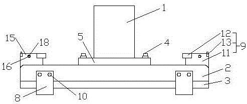
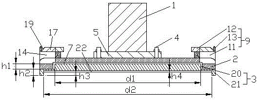
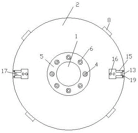
[0024] A transfer mechanism for wafer copper polishing, including a processing shaft 1, a shaft disc 2, a transfer disc 3 made of nylon material and bolts 4, wherein the bottom of the processing shaft 1 is provided with a connecting flange 5 , the connecting flange 5 is provided with a number of connecting holes 6, and the connecting holes 6 are evenly spaced around the connecting flange 5, and the bolts 4 pass through the connecting holes 6 and the shaft disk 2 to realize the processing of the shaft 1 and the shaft disk 5 connected, the bottom of the shaft disc 5 is provided with a first groove 7, and the shaft disc 7 is provided with a number of fastening plates 8 and ejection mechanisms 9, and the plurality of fastening plates 8 are evenly spaced around the shaft disc 2. Setting, the fastening plate 8 is provided with a fastening screw 10...


PUM


Abstract

The invention relates to a diverting mechanism used for copper polishing conditioning of a wafer. The diverting mechanism used for the copper polishing conditioning of the wafer comprises a machining shaft, a shaft disk, a diverting disk which is made of nylon material and bolts. A connecting flange is arranged at the bottom of the machining shaft. A first groove is formed in the bottom of the shaft disk. A plurality of fastening plates and ejecting mechanisms are arranged outside the shaft disk, wherein each ejecting mechanism comprises a supporting seat, an ejecting plate and a limiting block. A cavity is arranged in each supporting seat and guiding plates are arranged on both sides of each supporting seat. A through hole is formed in each guiding plate. One side of each ejecting plate is provided with a rotary plate and convexity screws are arranged on both sides of each rotary plate. The diverting disk comprises an upper disk and a lower disk, wherein the bottom of the lower disk is provided with a second groove and a cross-shaped square groove is formed in the second groove. The mechanism is reasonable in design, convenient to disassembly and assembly and high in practicability. Aimed at the differences between a small-sized machine and a large-sized machine, a large-sized ceramic disk can be diverted onto the small-sized machine for conditioning, so that the TTV of the wafer can be reduced, the requirement of flatness can be realized and the machining efficiency can be improved.

Description

technical field [0001] The invention relates to a transfer mechanism for wafer copper polishing and trimming, belonging to the technical field of sapphire substrate processing. Background technique [0002] Flatness is an important quality index in sapphire substrate processing. In the substrate processing process, copper polishing is an important process to shape the flatness of the wafer. It is the key to make the overall thickness difference (TTV) of the chip after chip placement. . [0003] In the copper polishing process, the heat generated by the grinding between the wafer and the diamond polishing fluid will cause the deformation of the disk surface, thereby affecting the flatness of the wafer. In the current copper polishing process, there are two mainstream equipment, one is suitable for A small model with a ceramic disc diameter of 355mm. This model is easier to control the flatness of the disc surface due to the smaller diameter of the copper disc surface. The TT...

Claims


Application Information

Patent Timeline
Patent Type & Authority Applications(China)
IPC IPC(8): B24B53/017
CPCB24B53/017
Inventor 姚钦王禄宝
Owner TUNGHSU GRP
Why Eureka
Try Eureka