
Electricity testing auxiliary device and system applied to 10/20kV overhead line

An auxiliary device and overhead line technology, applied in the direction of measuring devices, measuring electrical variables, indicating the existence of current/voltage, etc., can solve problems such as poor safety, dirty surfaces, and difficulty in ensuring firmness

Pending Publication Date: 2018-12-18
GUANGZHOU POWER SUPPLY BUREAU GUANGDONG POWER GRID CO LTD
View PDF9 Cites 0 Cited by
  • Summary
  • Abstract
  • Description
  • Claims
  • Application Information

AI Technical Summary

Problems solved by technology

[0002] The distribution network operation often needs to be tested on the 10kV / 20k pole tower. Generally, the total length of the 10 / 20kV electroscope pen is about 1.2 meters. Measuring live state of overhead line conductors
In order to meet the needs of the electric test operation under the tower, it is usually necessary to bundle the 110 / 220kV insulating rod and the 10 / 20kV test pen together for measurement, such as Figure 5 As shown, this method is neither safe nor compliant, and there are many security risks in such a bundling
On the one hand, the binding is done manually, and it is difficult to ensure the firmness
On the other hand, the binding method usually uses sticky tape for binding. In this way, after use, the sticky glue remains on the 110 / 220kV insulating rod, making the surface of the 110 / 220kV insulating rod dirty. The sticky glue has a certain conductivity, which will cause Reduce the insulation effect; and after use, the 10 / 20kV electric test pen holder also remains viscous colloid, which makes the surface dirty and reduces the insulation strength. It directly threatens the personal safety of the electric test personnel during the non-pole and tower electric test, making the safety poor
In addition, the existing bundling method is relatively complicated and the operation convenience is poor

Method used


Image

  • Electricity testing auxiliary device and system applied to 10/20kV overhead line
  • Electricity testing auxiliary device and system applied to 10/20kV overhead line
  • Electricity testing auxiliary device and system applied to 10/20kV overhead line

Examples


Embodiment Construction

[0024] In order to facilitate the understanding of the present invention, and to make the above objects, features and advantages of the present invention more obvious and understandable, the specific implementation manners of the present invention will be described in detail below in conjunction with the accompanying drawings. In the following description numerous specific details are set forth in order to provide a full understanding of the invention, and preferred embodiments of the invention are shown in the accompanying drawings. However, the present invention can be embodied in many different forms and is not limited to the embodiments described herein. On the contrary, the purpose of providing these embodiments is to make the disclosure of the present invention more thorough and comprehensive. The present invention can be implemented in many ways other than those described here, and those skilled in the art can make similar improvements without departing from the connota...


PUM


Abstract

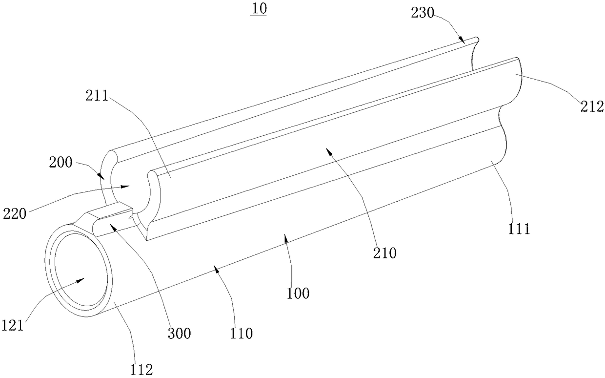
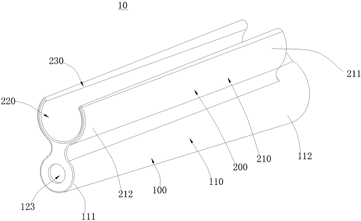
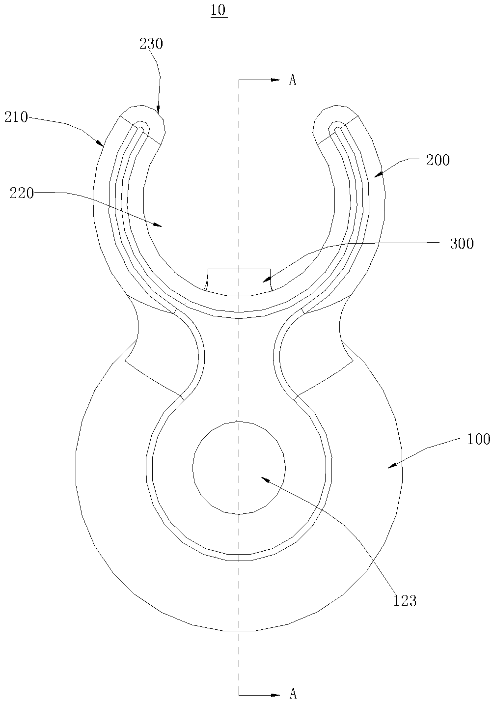
The invention discloses an electricity testing auxiliary device and system applied to a 10 / 20kV overhead line. The electricity testing auxiliary device comprises an electricity testing pen installation cylinder, an insulation rod installation cylinder and a positioning buckle; the diameter of each of the electricity testing pen installation cylinder and the insulation rod installation cylinder isgradually increased from one end part to the other end part; the outer side wall of the electricity testing pen installation cylinder is connected with the outer side wall of the insulation rod installation cylinder; a first electricity testing pen inserting hole, a second electricity testing pen inserting hole and a third electricity testing pen inserting hole which are connected in sequence areformed in the electricity testing pen installation cylinder; an insulation rod inserting hole is formed in the insulation rod installation cylinder; the diameter of the insulation rod inserting hole is gradually increased from one end to the other end; the positioning buckle is arranged on a side wall of the electricity testing pen installation cylinder; the positioning buckle is arranged close toone end, which is relatively small in diameter, of the insulation rod inserting hole; and the positioning buckle partially covers the insulation rod inserting hole. The electricity testing auxiliarydevice is used cooperatively with a 10 / 20kV electricity testing pen and a 110 / 220kV insulation rod, and is relatively good in operation convenience and relatively high in safety.

Description

technical field [0001] The invention relates to the technical field of electrical inspection assistance, in particular to an electrical inspection auxiliary device and system applied to 10 / 20 kV overhead lines. Background technique [0002] The distribution network operation often needs to be tested on the 10kV / 20k pole tower. Generally, the total length of the 10 / 20kV electroscope pen is about 1.2 meters. Measure the live state of overhead line conductors. In order to meet the needs of the electric test operation under the tower, it is usually necessary to bundle the 110 / 220kV insulating rod and the 10 / 20kV test pen together for measurement, such as Figure 5 As shown, this method is neither safe nor compliant, and there are many security risks in such a bundling. On the one hand, the binding is done manually, and it is difficult to ensure the firmness. On the other hand, the binding method usually uses sticky tape for binding. In this way, after use, the sticky glue rema...

Claims


Application Information

Patent Timeline
Patent Type & Authority Applications(China)
IPC IPC(8): G01R19/145G01R15/00
CPCG01R15/00G01R19/145
Inventor 韩海波马灿荣彭灵利吕泉成张新民缪新招邓明龚小东刘晓阳李义新高军伟
Owner GUANGZHOU POWER SUPPLY BUREAU GUANGDONG POWER GRID CO LTD
Learn More