Input device and method, information processing system, and program

a technology of input device and input method, applied in two-way working systems, high-level techniques, instruments, etc., can solve the problems of increasing power consumption, reducing the ease of operation rather than improving, and increasing the difficulty of detecting the remote controller, etc., to suppress the degradation of ease of operation, increase the power consumption, and reduce the effect of battery consumption

Active Publication Date: 2010-08-26
SONY CORP
View PDF7 Cites 25 Cited by
  • Summary
  • Abstract
  • Description
  • Claims
  • Application Information

AI Technical Summary

Benefits of technology

[0010]However, when the power supply to the angular velocity sensor or the acceleration sensor is stopped, holding of the remote controller becomes undetectable. As a result, it is necessary to continuously supply power to the angular velocity sensor or the acceleration sensor even when the remote controller is not in use. This results in an increase in the power consumption, and the batteries are more quickly consumed.
[0011]It is desirable to provide techniques that suppress degradation of the ease of operation and reduces power consumption.
[0012]According to an embodiment of the present invention, an input device includes an operation unit, a sending unit, and a power control unit. The operation unit is configured to be held by a user and to be operated in a three-dimensional free space so as to remotely operate an information processing apparatus. The sending unit is configured to send a command that disables display of a graphical user interface of the information processing apparatus when the operation unit is placed, and to send a command that...

Problems solved by technology

This degrades the ease of operation rather than improving it.
However, when the power supply to the angular velocity sensor or the acceleration sensor is s...

Method used


Image

  • Input device and method, information processing system, and program
  • Input device and method, information processing system, and program
  • Input device and method, information processing system, and program

Examples


first embodiment

System Configuration

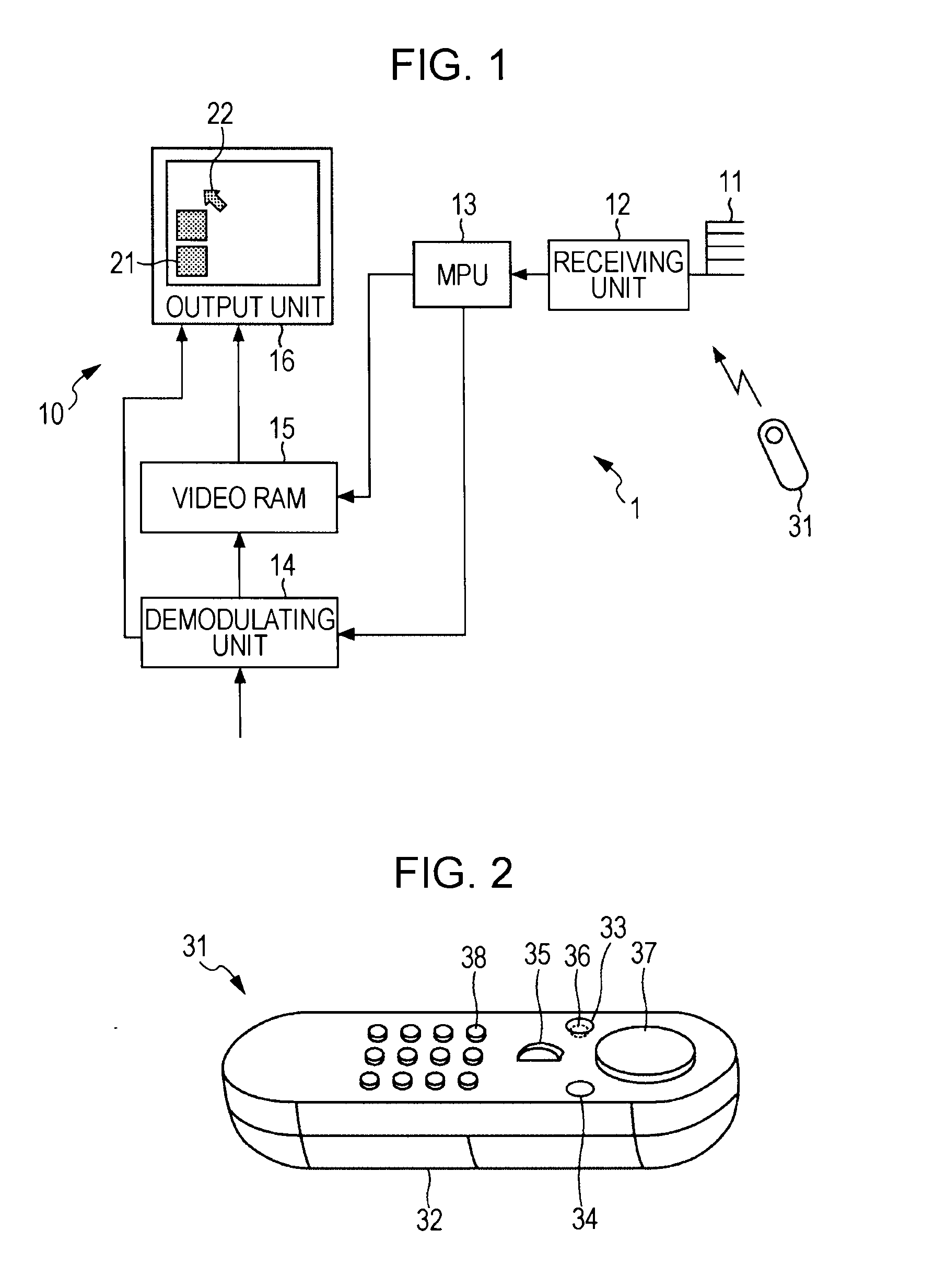
[0050]FIG. 1 is a block diagram illustrating a configuration of an information processing system according to an embodiment of the present invention.

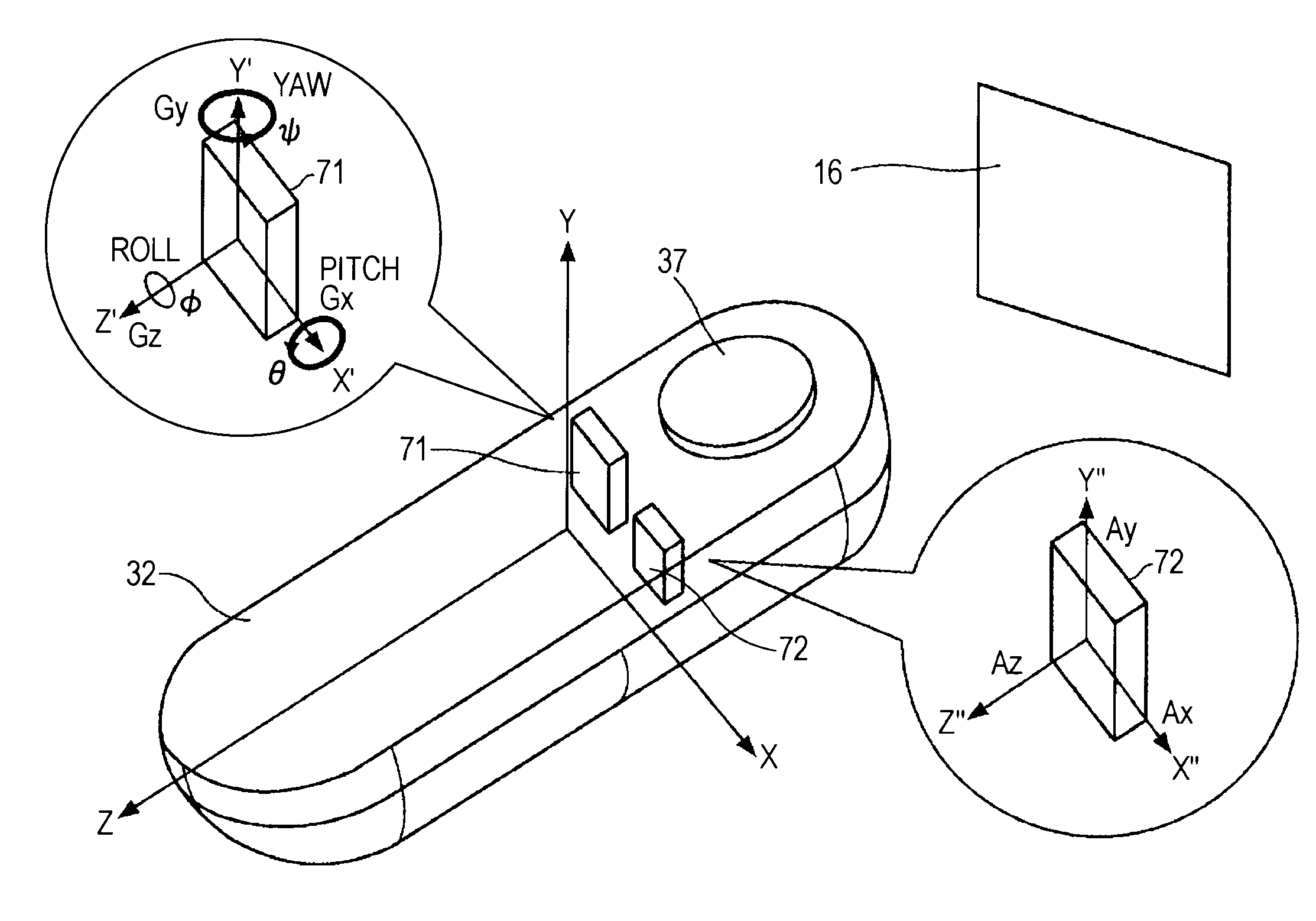
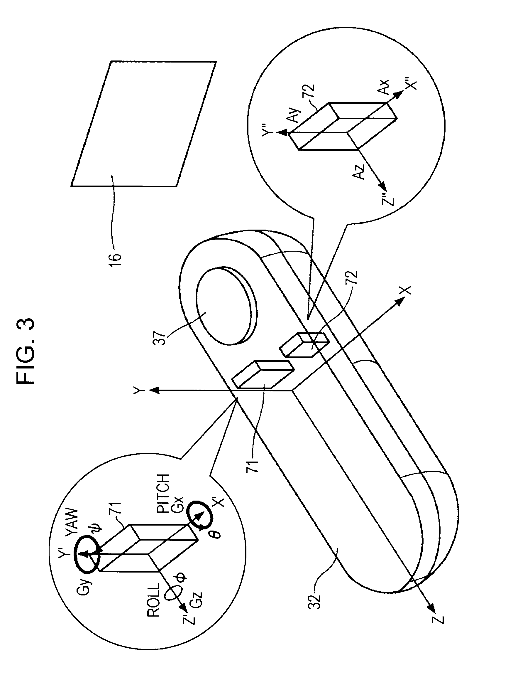
[0051]An information processing system 1 includes a television receiver 10 serving as an information processing apparatus and an input device 31 serving as a pointing device or a remote controller that remotely controls the television receiver 10.

[0052]The television receiver 10 includes an antenna 11, a receiving unit 12, a microprocessing unit (MPU) 13, a demodulating unit 14, a video random-access memory (RAM) 15, and an output unit 16.

[0053]The antenna 11 receives an electric wave from the input device 31. The receiving unit 12 demodulates the electric wave received via the antenna 11, and outputs the demodulated signal to the MPU 13. The MPU 13 controls each unit on the basis of an instruction from the input device 31.

[0054]The demodulating unit 14 demodulates a television broadcast signal received via a televis...

second embodiment

Second Command Sending Process Performed by Input Device

[0155]FIG. 18 is a flowchart describing another command sending process. The processing in steps S201 to S218 of FIG. 18 is basically similar to the processing in steps S11 to S28 of FIG. 7.

[0156]In the embodiment illustrated in FIG. 18, after it is determined that the operated button is the GUI start button in step S203, which corresponds to step S14 in FIG. 7, the process of turning on the activation power of the sensors 71 and 72 and reading editing data is executed in step S204, which corresponds to step S13 in FIG. 7.

[0157]In the embodiment illustrated in FIG. 7, when it is determined in the determining process in step S14 that the operated button is not the GUI start button, the standby process is executed until the GUI start button is operated. However, in the embodiment illustrated in FIG. 18, when it is determined in step S203 that the operated button is not the GUI start button, the sending unit 205 promptly executes ...

third embodiment

Structure of Input Device

[0160]FIG. 19 is a perspective view illustrating a structure of another input device in an embodiment. In the embodiment, the detection unit 39 for detecting holding of the main body 32 by the user is provided on a face other than the top face of the main body 32 (the right lateral face in the embodiment illustrated in FIG. 19). Unlike the top face, the right lateral face of the main body 32 is highly likely to be touched by a finger when the user holds the main body 32. By providing the detection unit 39 on the right lateral face, the user's holding, that is, placing of the input device 31, can be certainly detected.

[0161]Alternatively, the detection unit 39 may be additionally provided on the left lateral face of the main body 32. When two detection units 39 are provided on the two lateral faces, holding of the main body 32 by the user can be more certainly detected.

[0162]The detection unit 39 detects that the main body 32 is placed on the basis of the fac...


PUM


Abstract

An input device includes an operation unit, a sending unit, and a power control unit. The operation unit is configured to be held by a user and to be operated in a three-dimensional free space so as to remotely operate an information processing apparatus. The sending unit is configured to send a command that disables display of a graphical user interface of the information processing apparatus when the operation unit is placed, and to send a command that enables display of the graphical user interface of the information processing apparatus when a button of the operation unit is operated. The power control unit is configured to cause the input device to enter a low power consumption state when the operation unit is placed.

Description

BACKGROUND OF THE INVENTION[0001]1. Field of the Invention[0002]The present invention relates to an input device and method, an information processing system, and a program, and more particularly, to an input device and method, an information processing system, and a program that suppress deterioration of the ease of operation and reduce power consumption.[0003]2. Description of the Related Art[0004]The operation of television receivers is often controlled using graphical user interfaces. A graphical user interface is generally displayed on a television receiver when a user operates a predetermined button of a remote controller. When the button is operated again, the graphical user interface which has been displayed up to that moment is erased.[0005]However, when the user wishes to display the graphical user interface using such a remote controller, the user holds the remote controller and operates the button. When the user wishes to erase the graphical user interface, the user hold...

Claims


Application Information

Patent Timeline
IPC IPC(8): G06F3/01G06F1/32G09G5/00H04N7/173H04N21/41H04N21/431H04N21/442
CPCG06F1/3203G06F1/3259G06F3/0346G06F3/04842Y02B60/148Y02B60/1253Y02B60/32H04N21/42222H04N2005/4428Y02D10/00Y02D30/50
Inventor YAMAMOTO, KAZUYUKINIIKURA, HIDEO
Owner SONY CORP
Why Eureka
Try Eureka