Tape measures

Inactive Publication Date: 2005-02-15
FISCO TOOLS
View PDF11 Cites 22 Cited by
  • Summary
  • Abstract
  • Description
  • Claims
  • Application Information

AI Technical Summary

Benefits of technology

The provision of a pivotable switch of the length mentioned above allows the user to operate the braking means to brake or release the blade with ease. There are also other advantages associated with this feature and with preferred features. Such advantages and preferred features are mentioned below.
The provision of a pivotabl

Problems solved by technology

This maintenance of extension can be done manually by the user, for example, but this is inconvenient.
In

Method used


Image

  • Tape measures
  • Tape measures
  • Tape measures

Examples


Embodiment Construction

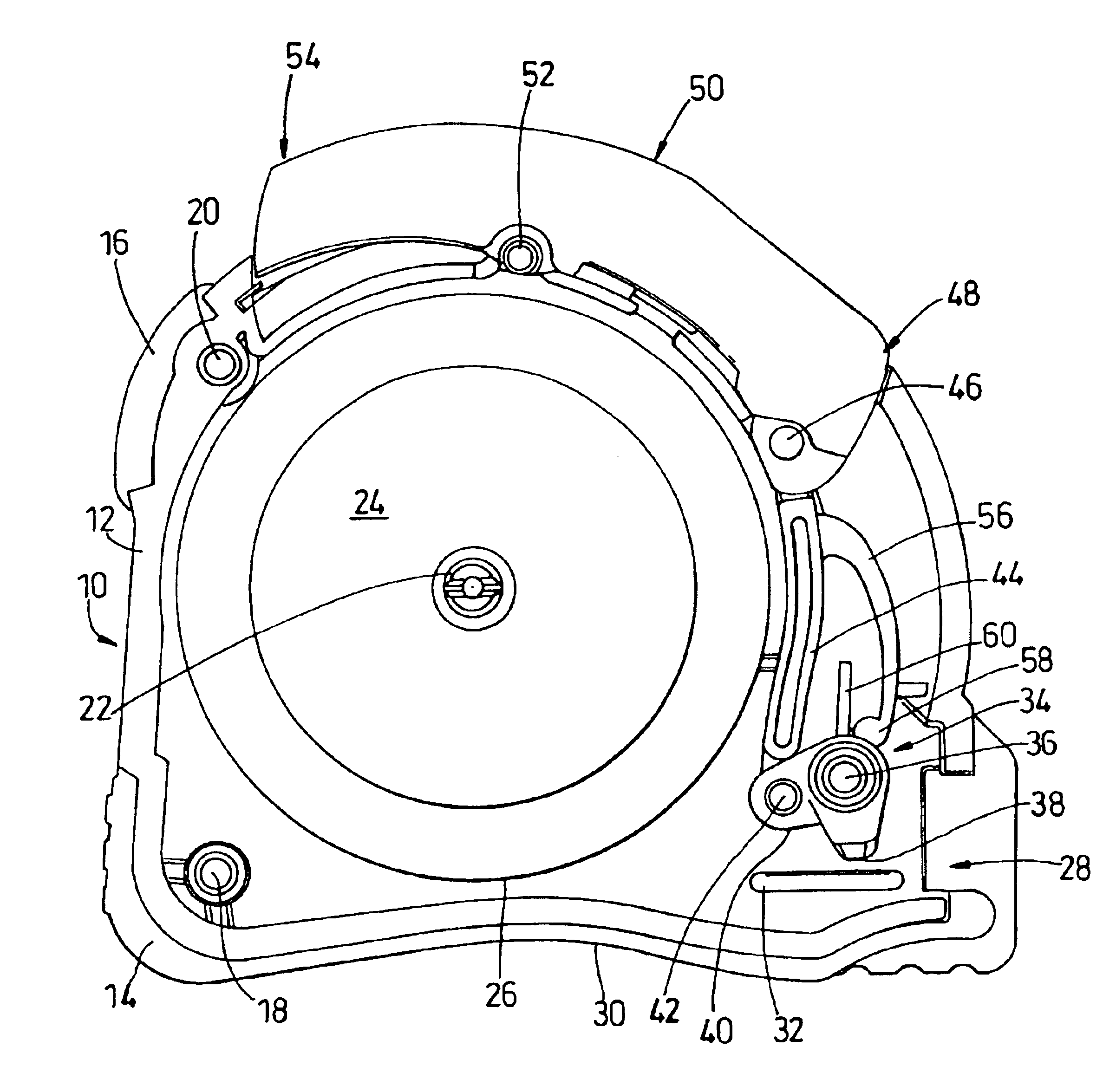
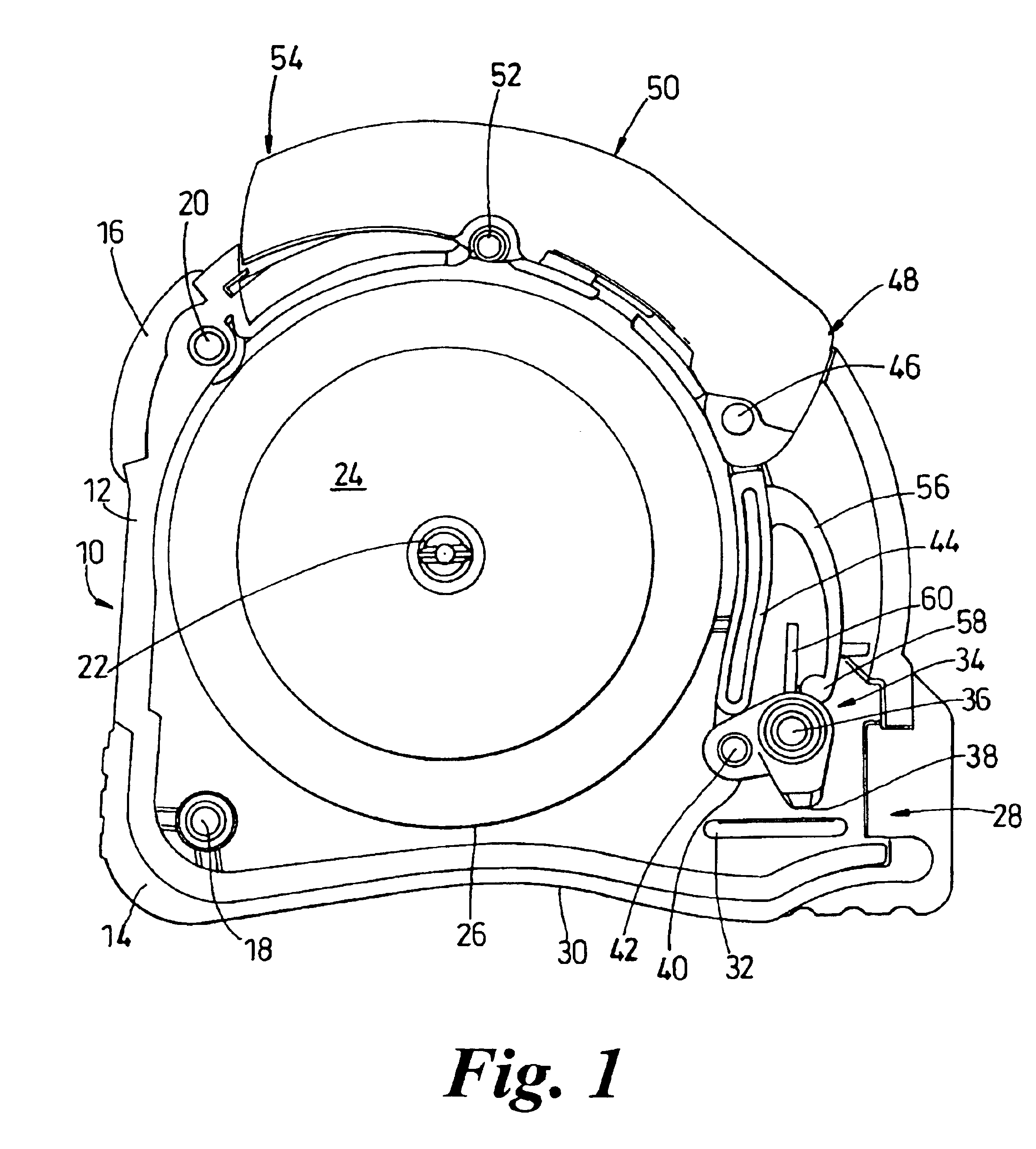
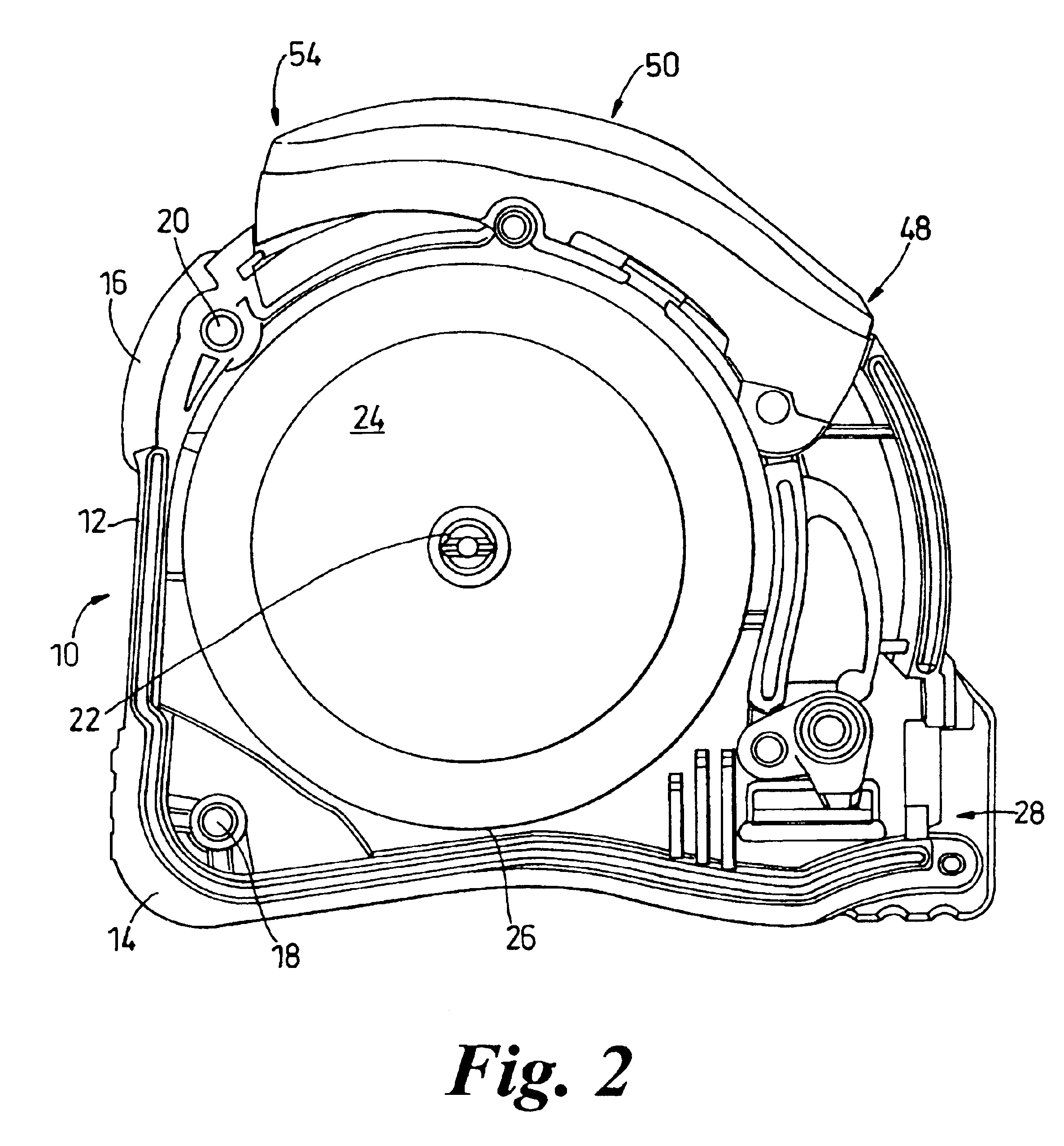
Reference is made in particular to FIG. 1, but also to FIGS. 2 and 3. Features which are shown in more than one drawing have been given the same reference numeral. All of the drawings show one half of a tape measure 10. The tape measure has a case 12 which is made from injection moulded plastics material, such as high impact ABS. The measure may also include outer features moulded into the case 12, such as shock-absorbent moulded pads 14,16, e.g. of rubber material (thermoelastic polymer). As shown in FIG. 1, the case 12 may be manufactured in two parts (only one part being shown in FIG. 1), the tape measure being constructed by subsequently fitting the two parts together via connection points 18,20,22,36.

The tape measure 10 includes a central mounting post 22. This post projects from a central region of the inner surface of the side wall 24 of the case. During assembly of the tape measure, the spooled measuring blade (not shown) is rotatably mounted on post 22. Circle 26 provides a...


PUM


Abstract

A tape measure is disclosed which has a spooled measuring blade mounted via a rotatable connection within a casing. The blade is extended from the case via an opening for use. The blade can be braked with respect to the opening by operation of braking means. The braking means are operable via a switch which has a length greater than the radius of the fully spooled blade. The switch is located and sized so that the brake can be engaged or disengaged by a user's hand without changing grip. The brake is a cam brake rotatably connected to the switch via a push-pull member.

Description

FIELD OF THE INVENTIONThe present invention relates to tape measures, and in particular to tape measures having a spooled measuring blade.BACKGROUND OF THE INVENTIONIn the description of the background of the present invention that follows reference is made to certain structures and methods, however, such references should not necessarily be construed as an admission that these structures and methods qualify as prior art under the applicable statutory provisions. Applicants reserve the right to demonstrate that any of the referenced subject matter does not constitute prior art with regard to the present invention.Known tape measures include tape measures having a metallic measuring blade which is spooled within a casing. The blade is extendable from the casing by pulling its free end. When released, the blade is automatically retracted back into the casing. Typically, this retraction is due to a spring within the casing, for example, a spring connected between the casing and a reel ...

Claims


Application Information

Patent Timeline
IPC IPC(8): G01B3/10G01B3/02
CPCG01B3/1005G01B2003/1046G01B2003/1035G01B2003/1015G01B3/1046
Inventor KNIGHT, JONATHAN ARNOLD MANLEY
Owner FISCO TOOLS
Why Eureka
Try Eureka