Monitoring system and dynamic detection equipment thereof for medium-low magnetic suspension train contact rail

A technology for magnetic levitation trains and dynamic detection, which is applied in railway auxiliary equipment, railway vehicle shape measuring instruments, measuring devices, etc., can solve the problems of inapplicability of detection equipment, large fluctuation, and detection failure.

Active Publication Date: 2012-08-01
BEIJING ENTERPRISES HLDG MAGLEV TECH DEV +1
View PDF5 Cites 31 Cited by
  • Summary
  • Abstract
  • Description
  • Claims
  • Application Information

AI Technical Summary

Problems solved by technology

[0005] However, the following technical problems exist when the above-mentioned detection device is applied to medium- and low-speed maglev trains: the bogie of medium- and low-speed maglev trains is a special structure in which the left and right modules are decoupled from each other and has a certain lateral anti-roll capability. There is relative movement of the modules, and correspondingly, the positional relationship between the bogie and the contact rail is affected by the suspension state and operation of the vehicle. Compared with the wheel-rail train, the fluctuation is larger, and the general detection equipment cannot be applied to this working condition
When the above-mentioned integral detection equipment for wheel-rail trains is transplanted and applied to the dynamic detection of the contact rail and current receiver of the medium and low-speed maglev train, the integral detection equipment will be twisted and deformed with the decoupling movement of the bogie, and the detection will fail, and eventually cause damage

Method used


Image

  • Monitoring system and dynamic detection equipment thereof for medium-low magnetic suspension train contact rail
  • Monitoring system and dynamic detection equipment thereof for medium-low magnetic suspension train contact rail
  • Monitoring system and dynamic detection equipment thereof for medium-low magnetic suspension train contact rail

Examples


Embodiment Construction

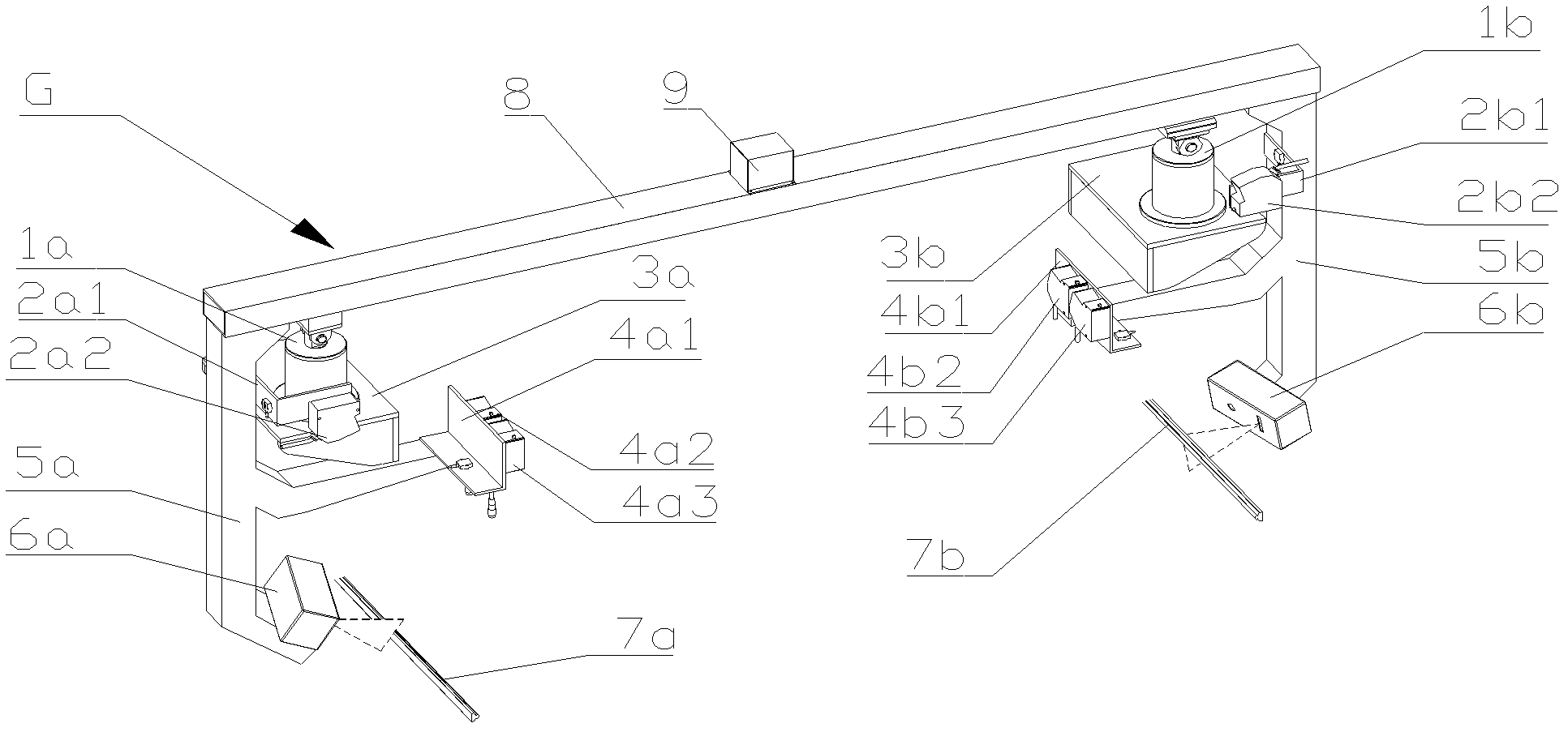
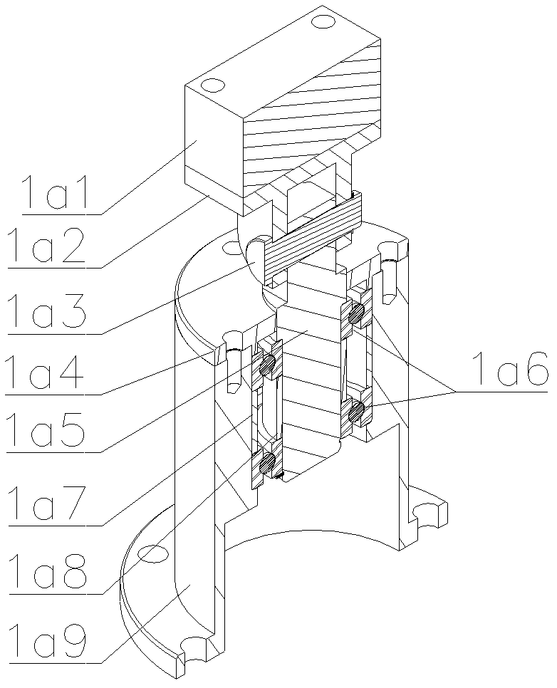
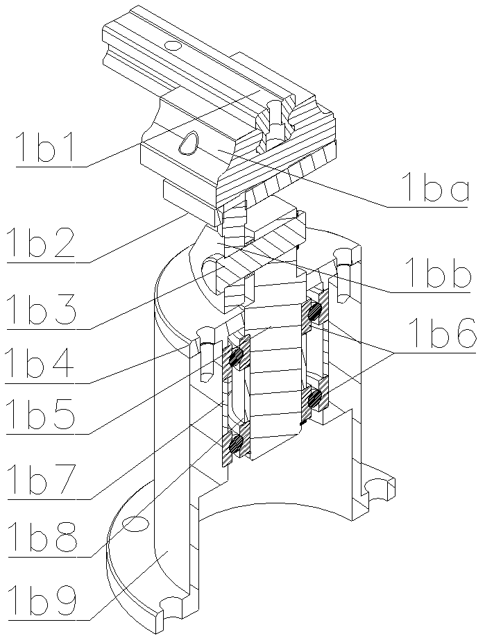
[0042] The core of the present invention is to provide a dynamic detection device for a contact rail of a medium-low speed maglev train. The detection device can be adapted to the dynamic working conditions of the bogie of this kind of train and truly reflect the real state of the contact rail.

[0043] In order to enable those skilled in the art to better understand the technical solutions of the present invention, the present invention will be further described in detail below in conjunction with the accompanying drawings and specific embodiments. For ease of understanding and brevity of description, the article combines the monitoring equipment of the contact rail of the medium and low-speed maglev train and its dynamic detection equipment for description, that is, the description of the overall monitoring system, and the beneficial effects will not be repeated. In addition, it should be noted that the "left" and "right" mentioned in the embodiments of the text all refer to ...


PUM


Abstract

The invention discloses a monitoring system and dynamic detection equipment thereof for a medium-low magnetic suspension train contact rail. The dynamic detection equipment disclosed by the invention comprises a left displacement detection device, a right displacement detection device and a fixing rack, wherein the left displacement detection device and the right displacement detection device are respectively used for detecting parameters of a left train gauge and parameters of a right train gauge so as to obtain the left gauge and the right gauge; both ends of the fixing rack are respectively used for mounting the left displacement detection device and the right displacement detection device and respectively rotationally connected as well as hinged with both sides of a bogie, the rotational axis lines in a vertical plane, and the hinge axis extends along a running direction; and one end of the fixing rack is in slip connection with the bogie along a track span direction. The dynamic detection equipment can be better suitable for a special bogie structure of a medium-low magnetic suspension train and can be correspondingly changed along with the dynamic working conditions of the bogie so as to truly react the working states of the contact rail in the running process of a train.

Description

technical field [0001] The invention relates to the technical field of maglev trains, in particular to a monitoring system for a contact rail of a medium-low speed maglev train and dynamic detection equipment thereof. Background technique [0002] Medium and low-speed maglev trains mainly use three or four rails for power supply and side contact current receiving, that is, contact rails (power supply rails) are set near the rails, and the current receivers installed on the train are in contact with the side of the contact rails, and the contact rails guide the current into the receiving rails. In order to achieve the purpose of providing electric energy for the train in real time. [0003] Due to external factors (such as misalignment and unevenness of the contact rail joint), or uneven wear of the collector shoe of the current collector, or unbalanced contact between the front and rear of the current collector, it is easy to cause poor contact between the current collector ...

Claims


Application Information

Patent Timeline
Patent Type & Authority Applications(China)
IPC IPC(8): B61K9/00G01B11/02G01B11/14
Inventor 周文武张兴华李中秀吴峻
Owner BEIJING ENTERPRISES HLDG MAGLEV TECH DEV
Why Eureka
Try Eureka