Lifting device for flywheel assembly

A flywheel and spreader technology, applied in the field of machinery, can solve the problems of time-consuming and laborious, inconvenient adjustment, difficult flywheel lifting, rotation adjustment, etc., to achieve the effect of convenient positioning, convenient adjustment and installation, and meeting adjustment requirements

Inactive Publication Date: 2012-08-01
KUSN MAIZHI FIXTURE TECH
View PDF5 Cites 10 Cited by
  • Summary
  • Abstract
  • Description
  • Claims
  • Application Information

AI Technical Summary

Problems solved by technology

If the flywheel is only manually installed without the help of a spreader, it is very time-consuming and laborious, and it is not easy to lift and rotate the flywheel to adjust the installation angle position
However, the current spreader is inconvenient to adjust, and it cannot realize the one-time hoisting and installation of the flywheel, and cannot meet the adjustment requirements of the installation process.

Method used


Image

  • Lifting device for flywheel assembly
  • Lifting device for flywheel assembly
  • Lifting device for flywheel assembly

Examples


Embodiment Construction

[0030] The present invention will be further described below in conjunction with the accompanying drawings. The following examples are only used to illustrate the technical solution of the present invention more clearly, but not to limit the protection scope of the present invention.

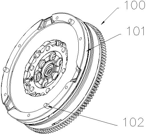
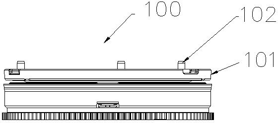
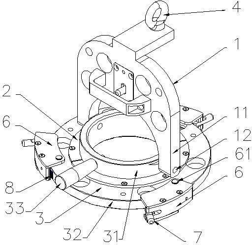
[0031] Such as image 3 , Figure 4 , Figure 5 and Figure 6 As shown, the flywheel assembly hanger of the present invention includes an inverted U-shaped hanger 1 , a rotating disk 2 and a main disk 3 . The turntable 2 and the main disk 3 are two socketed discs. The turntable 2 is connected to the main disk 3 and can rotate relative to the main disk 3 .

[0032] A suspension ring 4 is connected to the top of the hanger 1 for connection with the hoisting equipment; the ends of the two U-shaped legs 11 of the U-shaped hanger 1 are hinged on the turntable 2, so that the turntable 2 can go around the two U-shaped legs of the hanger 1 The connecting shaft 12 of 11 is a shaft rotation, and the ...


PUM


Abstract

The invention discloses a lifting device for flywheel assembly. The lifting device comprises an inverted U-shaped lifting frame, a turntable articulated with the lifting frame through a connecting shaft, and a main disc which is in cup joint with the turntable and can rotate relatively in the plane of the turntable, wherein the connecting shaft is parallel to the plane of the turntable, the main disc comprises an outer ring which can be sheathed at the edge of a flywheel, and the outer ring is provided with a rotatable buckle which can fasten the flywheel and the main disc together. When the flywheel is lifted up, the main disc can rotate in the horizontal direction freely so as to fix the position of the flywheel conveniently. After the flywheel is lifted to a corresponding position, the main disc and the flywheel rotate horizontally towards the vertical direction; meanwhile, the main disc still drives the flywheel to rotate freely in the direction of the plane of the main disc so that the flywheel can be matched with a machine body and adjusted to be assembled on the machine body conveniently. Through adoption of the lifting device, the one-time lifting and assembling process of the flywheel is realized and the requirement on the angle adjustment of the flywheel in the assembling process is met.

Description

technical field [0001] The invention relates to a flywheel assembly hanger, in particular to an engine flywheel assembly hanger, which belongs to the technical field of machinery. Background technique [0002] The flywheel is a larger disc-shaped part installed on the rear end of the crankshaft of the engine. It has a larger moment of inertia, such as figure 1 , figure 2 shown. When installing the flywheel, the disc-shaped flywheel needs to be erected for installation, and the flywheel needs to be able to rotate after being erected, and its angle can be adjusted to facilitate its cooperating installation with the body. If the flywheel is only manually installed without the aid of a spreader, it is very time-consuming and laborious, and it is not easy to lift and rotate the flywheel to adjust the installation angle position. However, the current spreader is inconvenient to adjust, cannot realize the one-time hoisting and installation of the flywheel, and cannot meet the a...

Claims


Application Information

Patent Timeline
Patent Type & Authority Applications(China)
IPC IPC(8): B66C1/10B66C13/04
Inventor 陈国栋
Owner KUSN MAIZHI FIXTURE TECH
Why Eureka
Try Eureka