A method for scribing a brittle material substrate

A technology for brittle material substrates and scoring lines, applied in stone processing tools, stone processing equipment, fine working devices, etc., can solve problems such as difficult-to-scratch grooves, glass substrates that cannot be used for scoring, and resin layer tearing. To achieve the effect of simplifying the work

Active Publication Date: 2012-08-01
MITSUBOSHI DIAMOND IND CO LTD
View PDF8 Cites 6 Cited by
  • Summary
  • Abstract
  • Description
  • Claims
  • Application Information

AI Technical Summary

Problems solved by technology

If you choose a cutter wheel with a ridgeline angle smaller than 90 degrees, the scoring groove will not be formed when the load is light, and the scoring groove will not be formed when the load is heavy, and it will suddenly crack in an irregular direction or produce horizontal cracks. In other cases, it is difficult to form a scribed groove smoothly
[0006] Conversely, if the cutter wheel with a large blade front edge ridgeline angle (blade angle 100-160 degrees) is rotated against a glass substrate with a resin layer formed on the surface, the force that the part of the blade front edge is pressed in the vertical direction is not only to the substrate , Also, if the resin layer becomes too large, a part of the resin layer that contacts the leading edge of the blade will be torn irregularly
[0007] Therefore, the glass substrate on which the resin layer is formed cannot be scribed using a general glass cutter wheel.

Method used


Image

  • A method for scribing a brittle material substrate
  • A method for scribing a brittle material substrate
  • A method for scribing a brittle material substrate

Examples


Embodiment Construction

[0040] Hereinafter, the scribing method of the glass plate of the present invention will be described in detail based on the drawings.

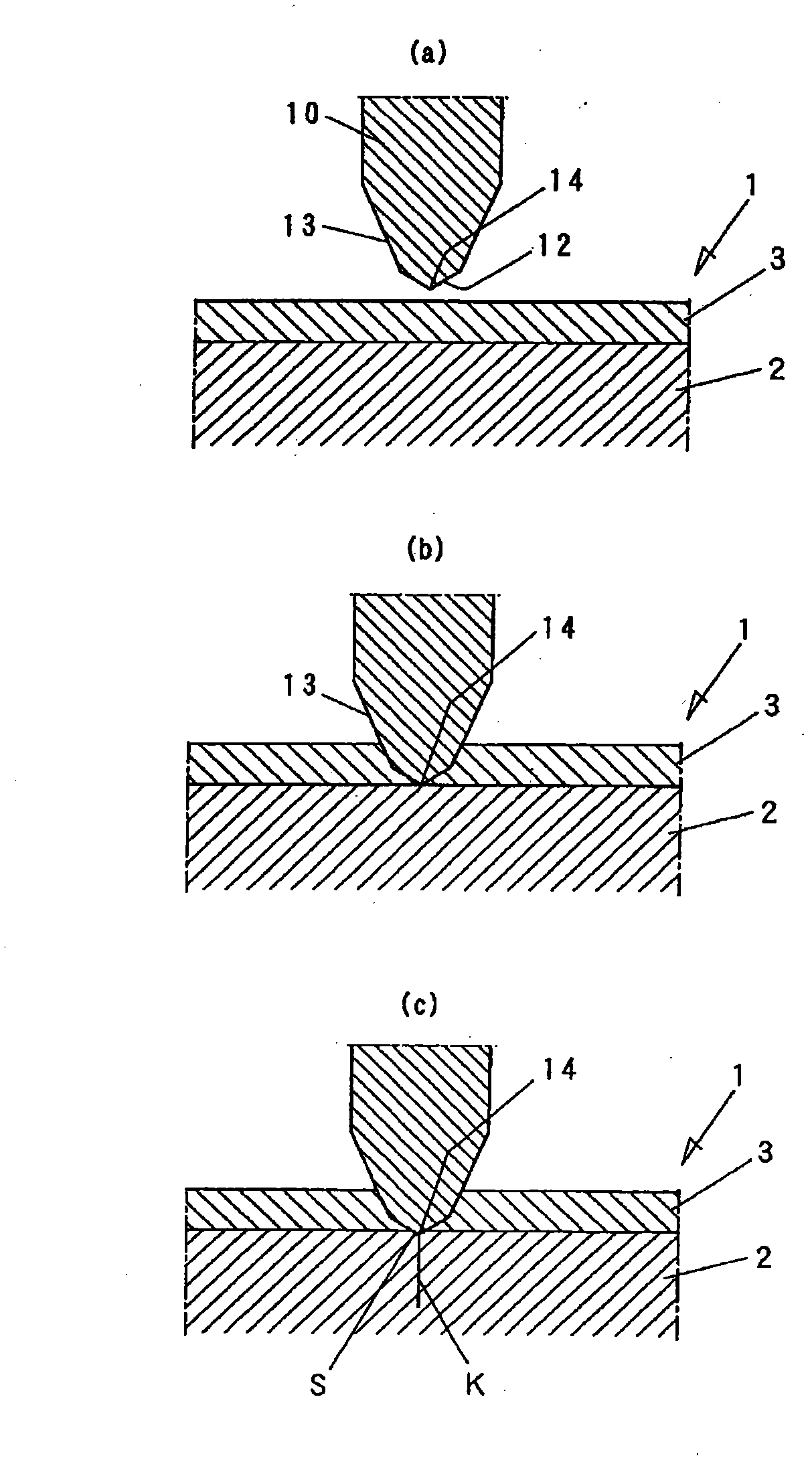
[0041] Here, as the substrate for scribing in the present invention, a thick colored glass plate for building materials having a resin layer on the surface will be described as an object. This colored glass plate 1, such as image 3 As shown, a thin resin layer 3 having a thickness of approximately 0.1 mm (as long as it is 0.05 mm to 0.2 mm) is provided on a glass material 2 having a thickness of 4 to 15 mm. The resin layer 3 includes a coating layer for imparting color or a protective resin film attached to it.

[0042] In addition, although horizontal cracks on the surface of the substrate for building materials are a problem, since the plate thickness is thick, the end face can be polished after being broken, so there is no need to care too much about the end face strength. Therefore, the difference in the end face strength required for the o...


PUM

PropertyMeasurementUnit
angleaaaaaaaaaa

Abstract

To provide a method for scribing a brittle material substrate, such as a glass substrate, on which a resin layer is formed according to which a scribe line can be created efficiently without fail. [Means for Achieving Object] A cutter wheel (10) with notches (15) having a blade surface with two parts: one part having a first blade surface (12) with a first ridgeline angle ( 1) between the left and right sides, the ridgeline being the outer periphery of the circular cutter wheel, and the other part having a second blade surface (13) that continues to the bottom of the first blade surface (12) on the left and right sides, where the first ridgeline angle ( 1) is appropriate for cutting a brittle material substrate and the second blade surface (13) has an angle appropriate for cutting the resin layer, is provided, and this cutter wheel (10) is rolled over and pressed against the upper surface of a resin layer (3) so that the resin layer (3) is cut by the second blade surface (13), and at the same time the blade ridgeline of the first blade surface (12) bites into the substrate so as to create a scribe line.

Description

Technical field [0001] The present invention relates to a scribing method for forming a scribe line (notch) on a brittle material substrate on which a coating layer coated with paint or resin is formed or a brittle material substrate on which a resin film layer is attached. [0002] In addition, the "resin layer" referred to in the following description includes not only a coating layer such as a resin film layer on the surface of the substrate, but also a coating layer coated with a paint or resin. Background technique [0003] When cutting a brittle material substrate such as glass, a scoring line is formed in advance along the predetermined breaking line. It is generally known that a knife wheel (also called a scoring wheel) is pressed against the surface of the substrate and is rotated. For example, it is disclosed in Patent Document 1 and the like. [0004] In order to form a scoring cutter wheel on the glass substrate, like Figure 4 The cutting edge ridge line 20 shown is proc...

Claims


Application Information

Patent Timeline
Patent Type & Authority Applications(China)
IPC IPC(8): C03B33/02C03B33/10
CPCC03B33/074B28D5/0011C03B33/107B28D1/225C03B33/02C03B33/033C03B33/037
Inventor 川畑孝志
Owner MITSUBOSHI DIAMOND IND CO LTD
Why Eureka
Try Eureka