Backward-flowing prevention air hammer drill for foam drilling

An anti-backflow and air hammer technology, applied in the field of oil and gas well drilling, can solve problems such as non-working, affecting normal drilling, and air hammer stuck, and achieve the effect of reducing drilling costs and reducing the number of trips.

Inactive Publication Date: 2012-08-01
PETROCHINA CO LTD
5 Cites 6 Cited by

AI-Extracted Technical Summary

Problems solved by technology

[0005] In order to solve the problem that formation water and cuttings flow back into the air hammer when the conventional air hammer is used in the field of foam drilling, causing sand sticking o...

Abstract

The invention provides a backward-flowing prevention air hammer drill for foam drilling. The backward-flowing prevention air hammer drill is characterized by comprising a tapered check valve, wherein the tapered check valve is arranged on the upper part of a center hole of the backward-flowing prevention air hammer drill and at the lower end of a tail pipe of the drill, and comprises a valve element body and a valve plug; the valve element body comprises a valve element and a pipe plug; the valve plug is in interference fit with the center hole of the backward-flowing prevention air hammer drill; the valve element is in clearance fit with the center hole of the drill; the valve element and the pipe plug form the valve element body with a hollow inner part; the valve element body can float up and down along a vertical direction between an upper dead center and a lower dead center; the upper dead center is the highest point for the upward floating of the valve element body along the vertical direction; and the lower dead center is the lowest point for the downward floating of the valve element body along the vertical direction.

Application Domain

Earth drilling toolsDrill bits

Technology Topic

EngineeringDrill bit +3

Image

  • Backward-flowing prevention air hammer drill for foam drilling
  • Backward-flowing prevention air hammer drill for foam drilling
  • Backward-flowing prevention air hammer drill for foam drilling

Examples

  • Experimental program(1)

Example Embodiment

[0022] The technical solutions in the embodiments of the present invention will be clearly and completely described below in conjunction with the accompanying drawings in the embodiments of the present invention. Obviously, the described embodiments are only a part of the embodiments of the present invention, rather than all the embodiments. Based on the embodiments of the present invention, all other embodiments obtained by those of ordinary skill in the art without creative work shall fall within the protection scope of the present invention.
[0023] The invention is provided with a conical check valve at the upper end of the center hole of the air hammer bit. When connecting a single root and stopping drilling for maintenance, if the two-phase fluid formed by formation water and cuttings enters the water hole of the bit, it can rely on buoyancy to force Close the one-way valve to block formation water and cuttings from entering the air hammer to avoid sand jams in the air hammer; during normal drilling, the one-way valve is open to ensure that there is enough foam media to reach the bottom of the well to cool the bit and force Carry rock.
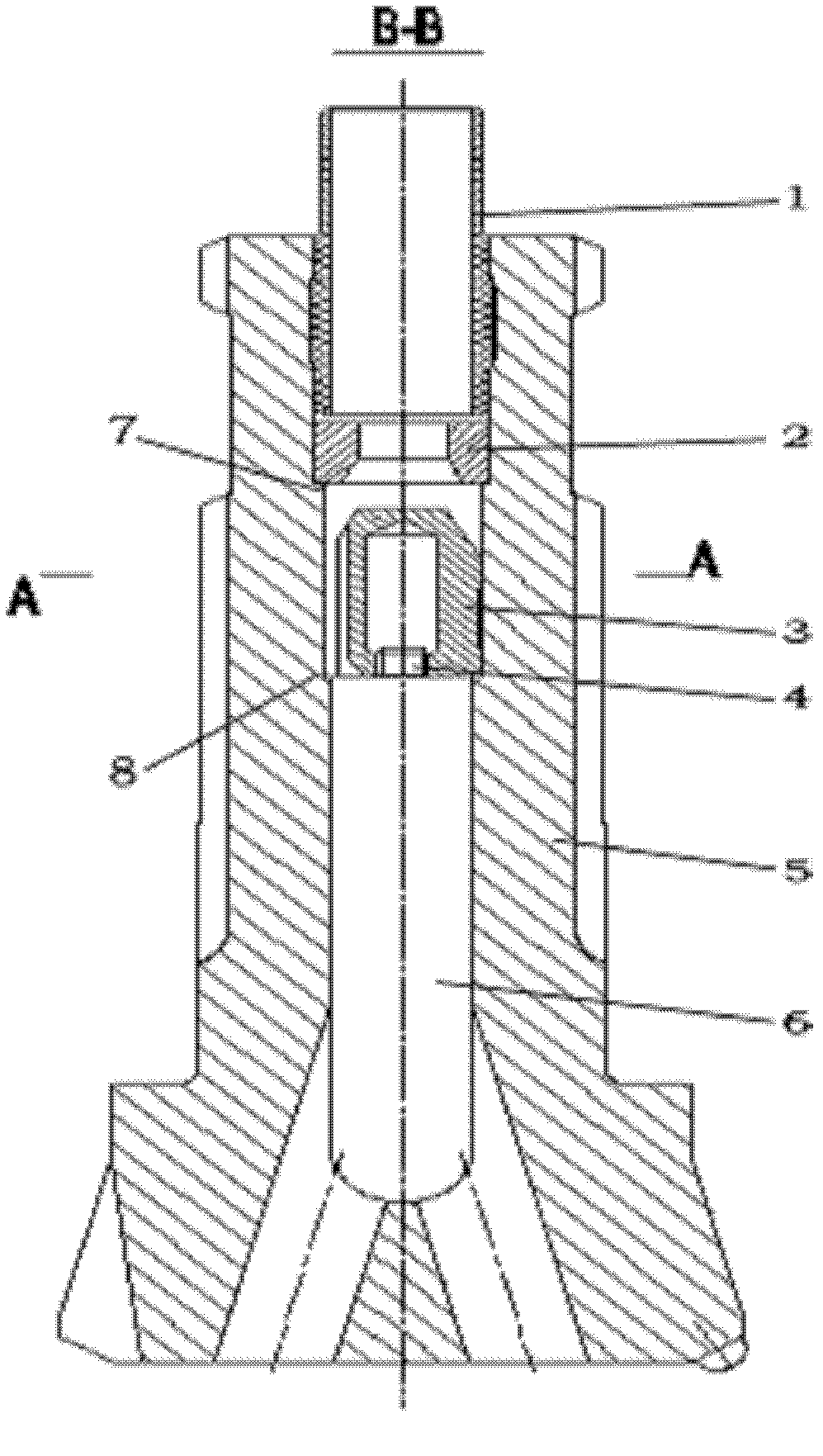
[0024] Such as figure 1 Shown is a schematic diagram of the structure of the anti-backflow air hammer drill bit 5 for foam drilling provided by the present invention (AA and BB in the figure represent cross-sectional views). At this time, the conical one-way valve is in the open state, that is, at the bottom dead center . A tapered check valve is provided on the upper part of the center hole 6 of the air hammer bit 5, which is located at the lower end of the tail pipe 1 of the bit. Cone one-way valve includes: valve plug 2, spool 3 and wire plug 4. The valve plug 2 and the drill center hole 6 are interference fit, and the valve core 3 and the drill center hole 6 are clearance fit.
[0025] The valve core 3 and the plug 4 form a hollow valve core body. The valve core body can float up and down between the top dead center 7 and the bottom dead center 8 in the vertical direction; wherein, the top dead center 7 is the highest point of the valve core body floating upward in the vertical direction, The bottom dead center 8 is the lowest point where the valve core body floats downward in the vertical direction. The specific gravity of the valve core body is less than that of water, ensuring that the valve core body floats up under the forced action of buoyancy, so that the outer cone of the valve core 3 and the inner cone of the valve plug 2 are closely matched to form a sealing cone (such as Figure 4 As shown, at this time, the conical one-way valve is in a closed state, that is, at the top dead center).
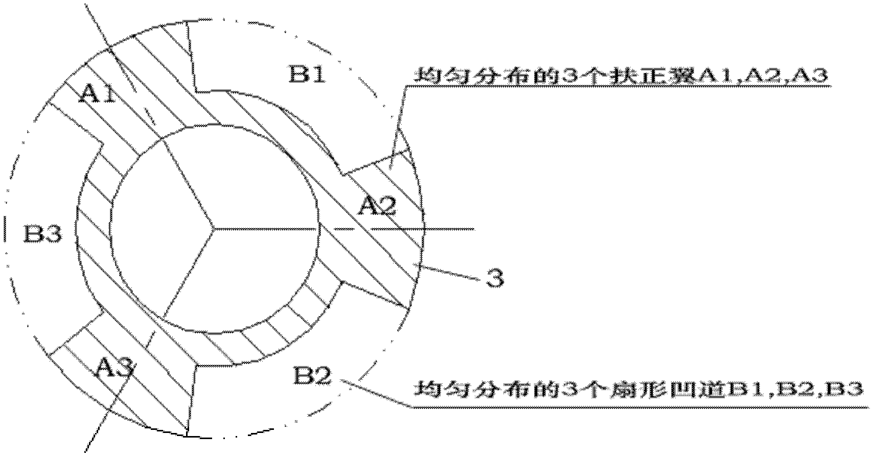
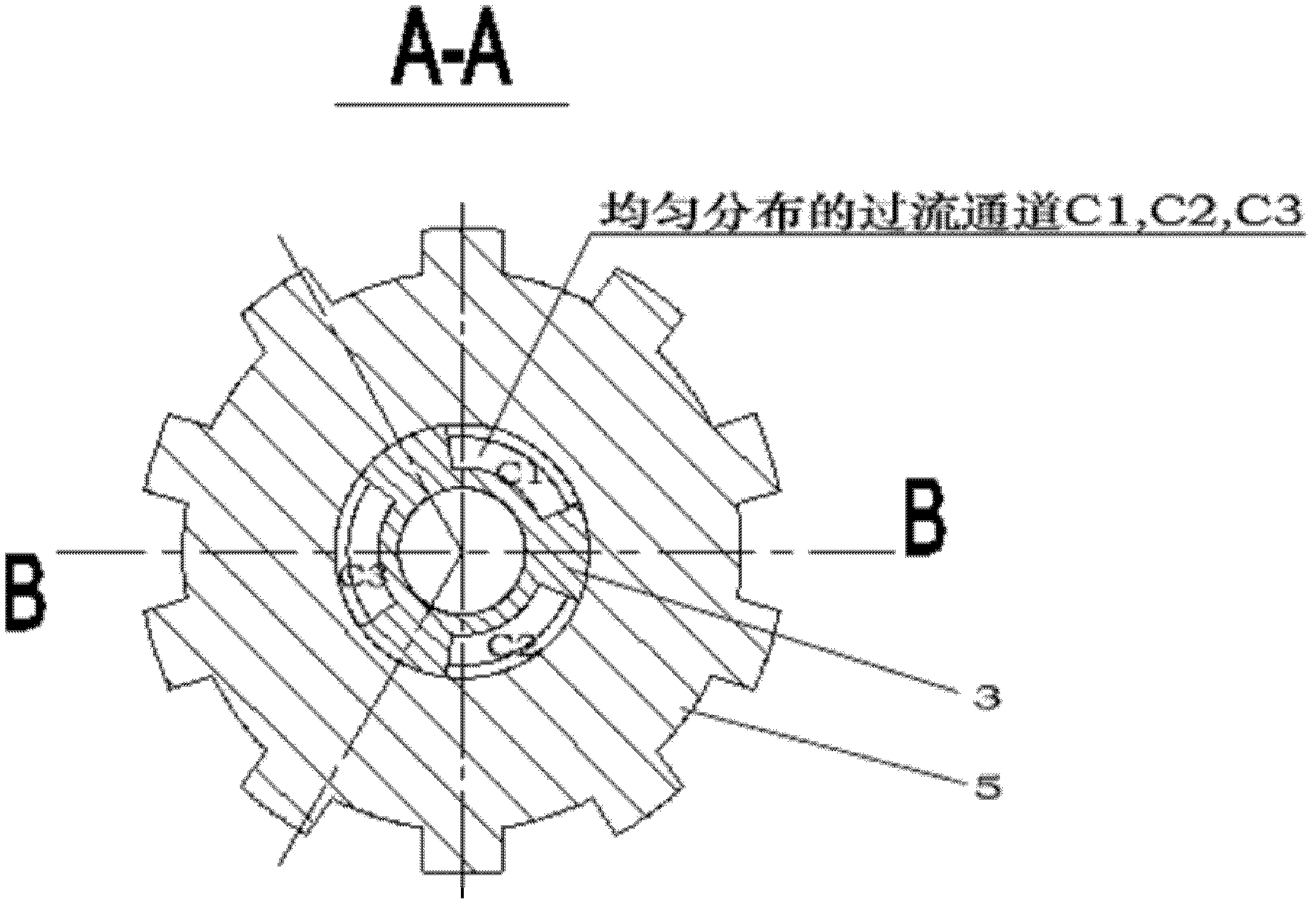
[0026] The upper part of the valve core body is a complete truncated cone, such as figure 2 As shown, the lower part of the valve core body is formed by two incomplete cylinders with three centralizing wings (A1, A2, and A3) and three fan-shaped grooves (B1, B2, and B3). Such as image 3 As shown, the sum of the circumferential angles of the three centralizing wings determines the size of the three flow channels (C1, C2, and C3) formed by the three fan-shaped grooves and the center hole of the drill bit. This value needs to be considered comprehensively. If too large , The flow channel will become smaller, and it is impossible to ensure that enough foam medium reaches the bottom of the well, which is not good for carrying rock and cooling the bit. If it is too small, although the flow channel becomes larger, it will affect the centralizing effect and the valve core body is easy to shift , It is not easy to float up and affect the sealing effect. For example, the sum of the circumferential angles of three centralizing wings is 135°, and the sum of the circumferential angles of the three fan-shaped grooves is 225°.
[0027] In order to ensure that the foam medium smoothly passes through the conical check valve without turbulence, the area of ​​the inlet channel of the conical check valve (that is, the area of ​​the center hole of the valve plug), the area of ​​the outlet channel (that is, the bottom end of the valve core and the center hole of the drill bit) The change between the formed passage area) and the flow passage area (that is, the passage area formed by the middle of the valve core and the central hole) should be minimized. For this reason, the inner arc of the fan-shaped recess in the lower part of the spool changes conically along the axial direction (such as figure 1 ) To make up for the impact of the reduced diameter of the drill center hole.
[0028] During normal drilling, the valve core body of the anti-backflow air hammer drill bit is at the bottom dead point 8 under the high pressure of the foam medium, and the conical one-way valve is opened (as shown in the figure), forming a gap between it and the center hole of the drill bit. The flow channel ensures that enough foam medium reaches the bottom of the well, which can carry the rock and cool the bit. When connecting a single root or stopping drilling, the valve core body floats up to the top dead point under the forced action of the buoyancy of the two-phase fluid formed by formation water and cuttings, and the conical one-way valve is closed (such as Figure 4 Shown), to achieve the purpose of sealing formation water and cuttings.
[0029] The application of the anti-backflow air hammer drill bit for foam drilling provided by the present invention can give full play to the advantages of air hammer drilling and foam drilling. Compared with ordinary air hammer bits, the present invention achieves the goal of preventing formation water and cuttings from pouring into the air hammer. Therefore, when drilling into formation water, there is no need to replace other drilling methods and drill normally, reducing the number of trips and trips. , Which reduces the drilling cost, and the strong rock-carrying and protection of the well wall of the foam media enable the air hammer to quickly penetrate the water layer.
[0030] Those skilled in the art can understand that the drawings are only schematic diagrams of a preferred embodiment.
[0031] Those skilled in the art can understand that the parts in the embodiment can be distributed in the device of the embodiment according to the description of the embodiment, or can be changed to be located in one or more devices different from this embodiment. The sequence numbers of the foregoing embodiments of the present invention are only for description, and do not represent the superiority of the embodiments.
[0032] In the present invention, specific examples are used to illustrate the principles and implementation of the present invention. The description of the above examples is only used to help understand the method and core idea of ​​the present invention; at the same time, for those of ordinary skill in the art, according to this The idea of ​​the invention will change in the specific implementation and the scope of application. In summary, the content of this specification should not be construed as limiting the invention.

PUM

no PUM

Description & Claims & Application Information

We can also present the details of the Description, Claims and Application information to help users get a comprehensive understanding of the technical details of the patent, such as background art, summary of invention, brief description of drawings, description of embodiments, and other original content. On the other hand, users can also determine the specific scope of protection of the technology through the list of claims; as well as understand the changes in the life cycle of the technology with the presentation of the patent timeline. Login to view more.

Similar technology patents

Transient electromagnetic advanced detection fixed point gyration antenna for tunnel

PendingCN107015283ALower Drilling CostsImprove tunneling efficiency
Owner:CHINA MERCHANTS CHONGQING COMM RES & DESIGN INST

Turbo-type high-frequency pulse pressurizer

PendingCN107355182AImprove rock breaking efficiencyLower Drilling Costs
Owner:YANGTZE UNIVERSITY

Column switch nest removing apparatus based on insulating rod

InactiveCN104882823AReduce phase-to-phase short circuitReduce the number of trips
Owner:YANTAI POWER SUPPLY COMPANY OF STATE GRID SHANDONG ELECTRIC POWER +1

Roller bit with roller pull-off prevention alarm apparatus

InactiveCN1464171APrevent falling offLower Drilling Costs
Owner:SOUTHWEST PETROLEUM UNIV

Transformer switching-on impulse current suppression device and method

PendingCN112713574AReduce the number of switch tripsReduce the number of trips
Owner:YONGJI XINSHISU ELECTRIC EQUIP

Closed circulation heating system

ActiveCN103453571AIncrease the heat exchange areaLower Drilling Costs
Owner:XI AN JIAOTONG UNIV

Classification and recommendation of technical efficacy words

  • Reduce the number of trips
  • Lower Drilling Costs

Column switch nest removing apparatus based on insulating rod

InactiveCN104882823AReduce phase-to-phase short circuitReduce the number of trips
Owner:YANTAI POWER SUPPLY COMPANY OF STATE GRID SHANDONG ELECTRIC POWER +1

Transformer switching-on impulse current suppression device and method

PendingCN112713574AReduce the number of switch tripsReduce the number of trips
Owner:YONGJI XINSHISU ELECTRIC EQUIP

Closed circulation heating system

ActiveCN103453571AIncrease the heat exchange areaLower Drilling Costs
Owner:XI AN JIAOTONG UNIV

Roller bit with roller pull-off prevention alarm apparatus

InactiveCN1464171APrevent falling offLower Drilling Costs
Owner:SOUTHWEST PETROLEUM UNIV

Transient electromagnetic advanced detection fixed point gyration antenna for tunnel

PendingCN107015283ALower Drilling CostsImprove tunneling efficiency
Owner:CHINA MERCHANTS CHONGQING COMM RES & DESIGN INST

Turbo-type high-frequency pulse pressurizer

PendingCN107355182AImprove rock breaking efficiencyLower Drilling Costs
Owner:YANGTZE UNIVERSITY
Why Eureka
Try Eureka