
Underground pressure monitoring device

A technology for monitoring system and downhole pressure, which is applied in measurement, wellbore/well components, earthwork drilling and production, etc. It can solve the problems of lower downhole accident rate, low anti-noise interference ability, low transmission rate, etc., so as to reduce maintenance time The effect of low cost, strong anti-noise interference ability, and fast transmission rate

Active Publication Date: 2017-04-26
CHINA UNIV OF PETROLEUM (EAST CHINA)
View PDF4 Cites 4 Cited by
  • Summary
  • Abstract
  • Description
  • Claims
  • Application Information

AI Technical Summary

Problems solved by technology

[0005] The present invention aims at the above-mentioned problems of high cost, low transmission rate and low anti-noise interference ability existing in the monitoring of downhole pressure in the prior art, and provides a downhole pressure sensor with low cost, fast transmission rate, strong anti-interference ability and high reliability. Monitoring system, which can measure the pressure in the drill string and the annular space in real time, and transmit the downhole data to the ground through acoustic wave transmission, so as to realize real-time monitoring of the bottomhole pressure, thereby reducing the incidence of downhole accidents and the risk of drilling operations

Method used

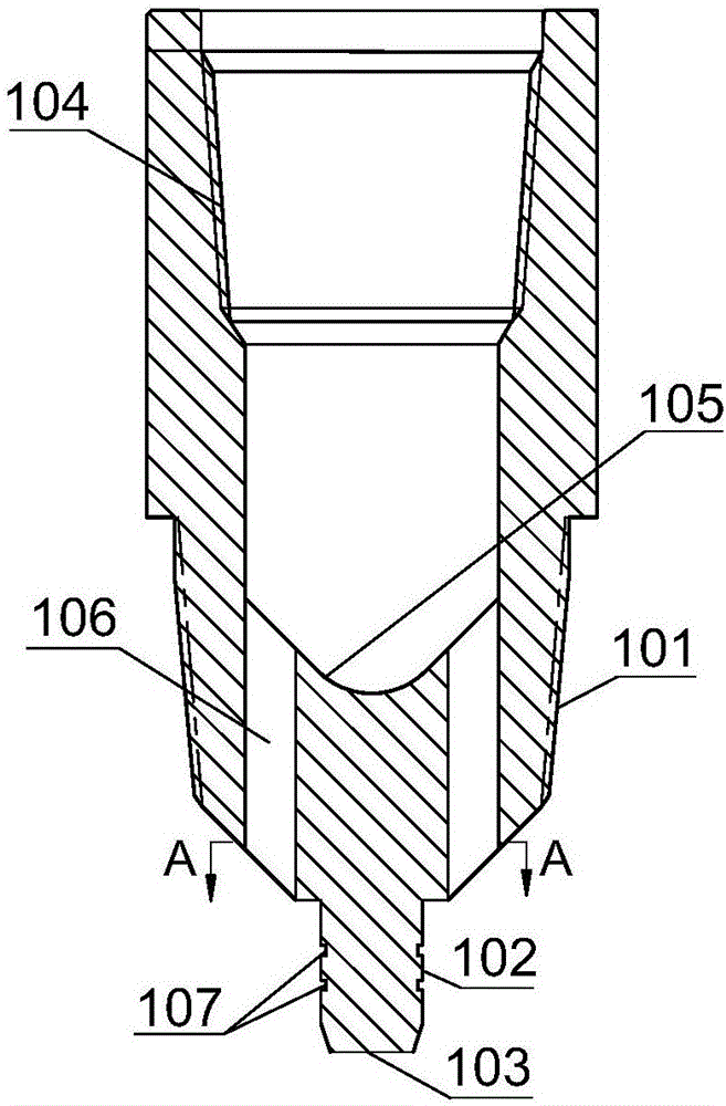
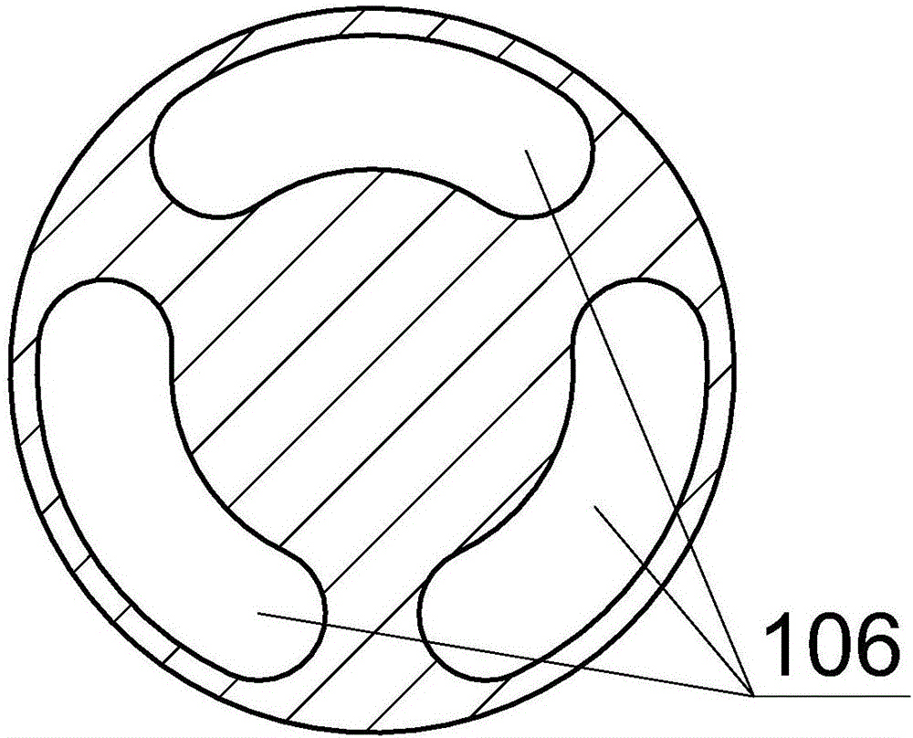

Image

  • Underground pressure monitoring device
  • Underground pressure monitoring device
  • Underground pressure monitoring device

Examples


Embodiment Construction

[0050] In the following, the present invention will be specifically described through exemplary embodiments. It should be understood, however, that elements, structures and characteristics of one embodiment may be beneficially incorporated in other embodiments without further recitation.

[0051] In the description of the present invention, it should be noted that the orientations or positional relationships indicated by the terms "inner", "outer", "upper", "middle", and "lower" are based on the positional relationships shown in the drawings, and only It is for the convenience of describing the present invention and simplifying the description, but does not indicate or imply that the referred device or element must have a specific orientation, be constructed and operated in a specific orientation, and thus should not be construed as limiting the present invention. In addition, the terms "first", "second", "third", "fourth", "fifth", and "sixth" are used for descriptive purpose...


PUM


Abstract

The invention relates to an underground pressure monitoring device. The underground pressure monitoring device comprises an energy converter, an energy converter driving circuit, an encoding transcoding circuit, an annular pressure measuring element and a drill column internal pressure measuring element, wherein the energy converter, the energy converter driving circuit and the encoding transcoding circuit are connected with each other in turn; the annular pressure measuring element and the drill column internal pressure measuring element are respectively connected with the encoding transcoding circuit; an annular pressure signal measured by the annular pressure measuring element and a drill column internal pressure signal measured by the drill column internal pressure measuring element are transmitted to the encoding transcoding circuit for encoding and transcoding; the transcoded pressure signal is transmitted to the energy converter driving circuit for driving the signal; the energy converter is driven by the energy converter driving circuit to convert the transcoded pressure signal into a sound wave signal and then send the sound wave signal. The underground pressure monitoring device can achieve the purpose of accurately real-time converting the underground pressure into the sound wave signal while normally drilling; the drill column is used as a transmission channel and is independent of the drilling liquid; the noise jamming resistance is high; the transmission rate is high and the error rate is low; the underground pressure monitoring device is not influenced by the underground complex conditions, such as, gas invasion.

Description

technical field [0001] The invention belongs to the technical field of oil and natural gas drilling engineering, and relates to a monitoring system while drilling, in particular to a downhole pressure monitoring system based on acoustic wave transmission, which is used for real-time monitoring of downhole pressure. Background technique [0002] According to the current status of oil and gas resources development in the world, the development of oil and gas resources has shifted from conventional oil and gas reservoirs to unconventional oil and gas reservoirs, from shallow formations to deep formations, and from land to ocean deep water and ultra-deep water areas. This will make the future oil drilling industry encounter Due to the severe challenges of more complex geological conditions and harsher natural environment, higher requirements are put forward for the safety of oil and gas drilling. [0003] During the drilling process, abnormal bottomhole pressure is the main caus...

Claims


Application Information

Patent Timeline
Patent Type & Authority Applications(China)
IPC IPC(8): E21B47/06E21B47/16
CPCE21B47/06E21B47/16
Inventor 管志川王庆刘永旺张波胜亚楠
Owner CHINA UNIV OF PETROLEUM (EAST CHINA)
Learn More