Kite wind power generation system

A wind power generation system and kite technology, which is applied to wind power generation, wind turbines, wind turbine combinations, etc., can solve the problems of poor control stability, poor power quality, and high power generation costs, and achieve the effect of simple and easy cost.

Inactive Publication Date: 2012-08-01
李永平
View PDF0 Cites 2 Cited by
  • Summary
  • Abstract
  • Description
  • Claims
  • Application Information

AI Technical Summary

Problems solved by technology

[0002] The use of wind energy is one of the main ways to develop green energy. At present, the main way to use it is to build large wind turbines to obtain wind power generation. Wind energy, high cost of power generation, poor power quality
The wind speed at high altitude is faster and the wind power is more stable, which means that if wind energy is obtained from high altitude for power generation, it can provid

Method used


Image

  • Kite wind power generation system
  • Kite wind power generation system
  • Kite wind power generation system

Examples


Example Embodiment

[0026] Example 1 Kite wind power generation device with vertical turntable

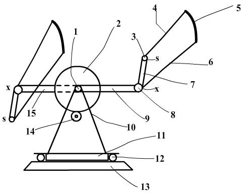
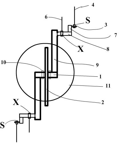
[0027] This example is described in conjunction with Figure 2, Figure 3, and Figure 4. Figure 2 is a side view of the turntable placed vertically, and Figure 3 is a top view of the device. In Figure 2, the turntable is composed of a rotating arm 9 and a rotating arm 15 around the central shaft 1. The rotating arm 9 and the rotating arm 15 are respectively located on both sides of the gear 2, and the angle between the two rotating arms is 180 degrees. It is supported by feet 10 and installed on a horizontal platform 11 that can rotate 360 ​​degrees, and the rotating platform is installed on a base 13. At the end of the swing arm, a rear control line tethering shaft 8 is installed. On the head of the shaft 8, an arm 7 with an angle greater than 90 degrees between the swing arm is installed. At the end of the support arm 7, The front control spool 3, the front control line 4 and the rear control line 6 o...

Example Embodiment

[0031] Example 3 Kite wind power generation device with horizontal turntable

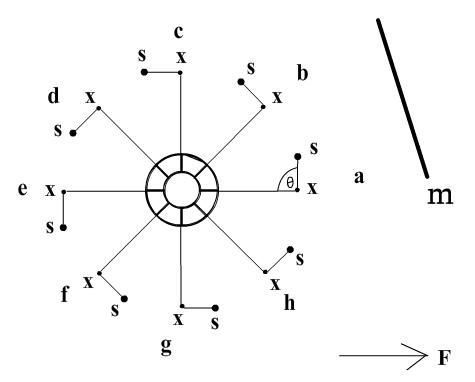
[0032] This example is illustrated in conjunction with Figure 6. In Figure 6, the turntable is composed of four spiral arms 68 surrounding the central axis of rotation 61 of the turntable. The inner end of the spiral arms is mounted on the shaft 61. The four spiral arms are on the same surface of the horizontal plane. The four spiral arms are equally divided into a circle. The shaft 61 is installed on the base 610, and the lower part of the rotating shaft is equipped with a gear 69, which transmits the power of the turntable to the power generator 611 to generate electricity. On the outer end of each swing arm 68, a rear control wire mooring shaft 63, 63 is installed on the outer end of the support arm 66, 66 at an angle of 90 to 180 degrees with the swing arm, and a front The control line is tied to the shaft 64, the front control line of the kite 62 is tied to the shaft 64 through the mooring point ...


PUM


Abstract

The invention mainly provides a kite wind power generation system, which is capable of driving a turntable on the ground to rotate continuously by utilizing pull force provided by a kite or a kite unit in the air so as to drive a generator to generate power. The kite wind power generation system comprises a ground part and an air part, wherein the ground part is mainly provided with the turntable, and a kite posture control mechanism, a rotary platform, a power transiting and acting device and the like on the turntable; and the air part comprises types of kites, blank ways of kites and the like. The kite wind power generation system disclosed by the invention is capable of enabling postures of kites in the air to be at different phase positions along with rotation of the turntable on the ground so as to be changed automatically, therefore, the kite wind power generation system is capable of driving the turntable to rotate continuously and obtaining power for foreign work, such as power generation.

Description

technical field [0001] The invention relates to a kite wind power generation system, which belongs to the energy field of wind kinetic energy utilization. Background technique [0002] The use of wind energy is one of the main ways to develop green energy. At present, the main way to use it is to build large wind turbines to obtain wind power generation. Wind energy makes power generation cost high and power quality poor. The wind speed at high altitude is faster and the wind power is more stable, which means that if wind energy is obtained from high altitude for power generation, it can provide wind power with lower cost and better quality. People all over the world have proposed some schemes to utilize high altitude wind energy, including Kites and umbrellas are used to drive ground generators to generate electricity, but so far there has been no major breakthrough for commercial development and utilization. The reasons are that the technology is too complicated and the c...

Claims


Application Information

Patent Timeline
IPC IPC(8): F03D9/00F03D7/00A63H27/08
CPCY02E10/723Y02E10/725Y02E10/72
Inventor 李永平
Owner 李永平
Why Eureka
Try Eureka