

Optimization method for industrial circulating water system
A technology of industrial circulating water and circulating water system, which is applied in the pipeline system, energy industry, sustainable manufacturing/processing, etc., and can solve the problem of overcooling of the heat exchange surface of the heat exchanger, system running, popping, dripping, leaking, and system failure. problems such as elevated pressure
Active Publication Date: 2012-08-01
CHANGSHA HAICHUAN ENERGY SAVING TECH
View PDF6 Cites 9 Cited by
- Summary
- Abstract
- Description
- Claims
- Application Information
AI Technical Summary
Problems solved by technology
[0003] 1) The cooled medium is too cold, which affects the production efficiency of the subsequent process;
[0004] 2) The heat exchange surface of the heat exchanger is too cold, which may easily lead to fouling, slagging, and ash sticking, which will affect the life of the heat exchanger;
[0005] 3) Excess supply of circulating water is a waste of energy;
[0006] 4) Excessive flow often leads to an increase in system pressure, which can easily lead to running, popping, dripping, and leaking of the system, affecting the service life of the en
Method used
View moreImage
Smart ImageViewing Examples

Examples
 PUM
 Abstract
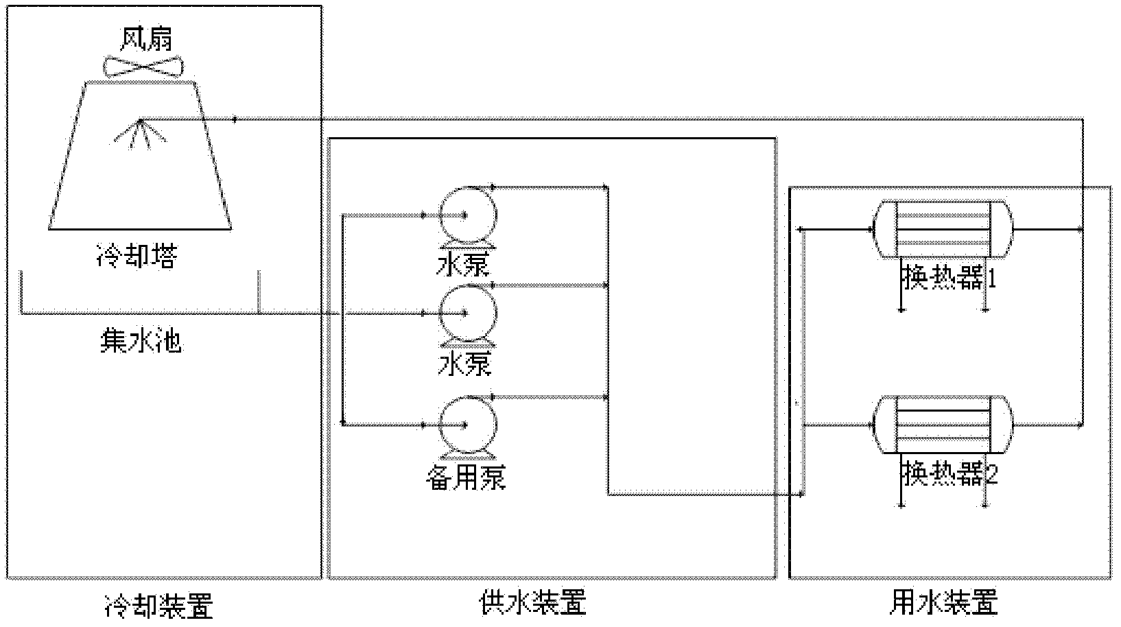
The invention discloses an optimization method for an industrial circulating water system. The optimization method comprises the following steps: 1, carrying out field measurement on the inlet and outlet temperature and the mass flow-rate of a cooling medium and a cooled medium in a heat exchanger in the circulating water system, and the input energy of water supply equipment; 2, according to themeasurement data, determining the optimal mass flow-rate of the cooling medium in each heat exchanger, and according to the height difference and the temperature of the least favorable point of the system, determining the optimal pressure of the system; and 3, according to the obtained optimal mass flow-rate of the cooling medium and the obtained optimal pressure of the system, estimating and calculating the savable energy of a pump house by using an energy consumption balance method to determine whether the equipment is replaced or not, and if the savable energy is more than 5% of the input energy, considering the reconfiguration of the equipment. According to the optimization method, the optimal water supply amount and the necessary minimum pressure can be accurately calculated and the system is controlled to reach the requirements, the energy can be saved for the circulating water supply equipment, the running life of the system can be prolonged, and the production process is more reasonable.
Description
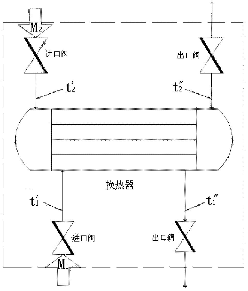
technical field [0001] The invention belongs to an industrial circulating water system, and in particular relates to an optimization method of an industrial circulating water system. Background technique [0002] At present, the circulating water systems of most industrial and mining enterprises only stay at the level of guaranteed production. Due to various reasons, the energy of most circulating water systems has not been fully utilized during operation, with low energy efficiency and high energy consumption. rate, only reached 25% to 40%. For example, the inlet temperature t′ of the cooled medium of the key equipment heat exchanger in the circulating water system 1 , outlet temperature t″ 1 In many cases less than the design value, which can lead to the following problems: [0003] 1) The cooled medium is too cold, which affects the production efficiency of the subsequent process; [0004] 2) The heat exchange surface of the heat exchanger is too cold, which may easil...
Claims
Login to View More Application Information
Patent Timeline
 IPC IPC(8): F17D3/01F17D1/14
CPCY02P80/10
Inventor张智勇
OwnerCHANGSHA HAICHUAN ENERGY SAVING TECH