Concrete beam reverse loading test device

A technology of reverse loading and testing device, applied in the direction of measuring device, testing of machine/structural components, instruments, etc., can solve the problems of inconvenient measurement of crack width and unfavorable experimental data, and achieve convenient and accurate loading control, arbitrary movement, simple structure

Inactive Publication Date: 2012-08-01
CHINA THREE GORGES UNIV
View PDF8 Cites 22 Cited by
  • Summary
  • Abstract
  • Description
  • Claims
  • Application Information

AI Technical Summary

Problems solved by technology

The problem with this device is that it is inconvenient to observe the trend of the crack at the bottom of the beam and measure the width of the crack, which is not conducive to the acquisition of experimental data

Method used


Image

  • Concrete beam reverse loading test device
  • Concrete beam reverse loading test device
  • Concrete beam reverse loading test device

Examples


Embodiment Construction

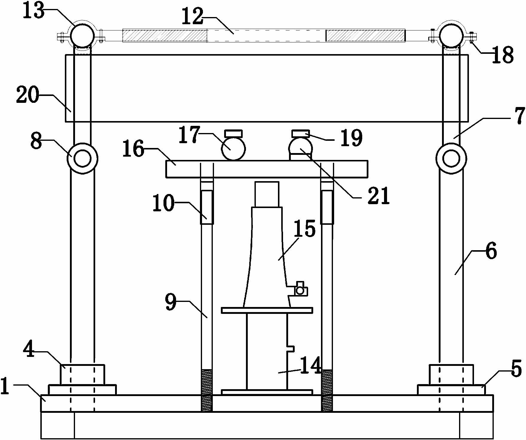
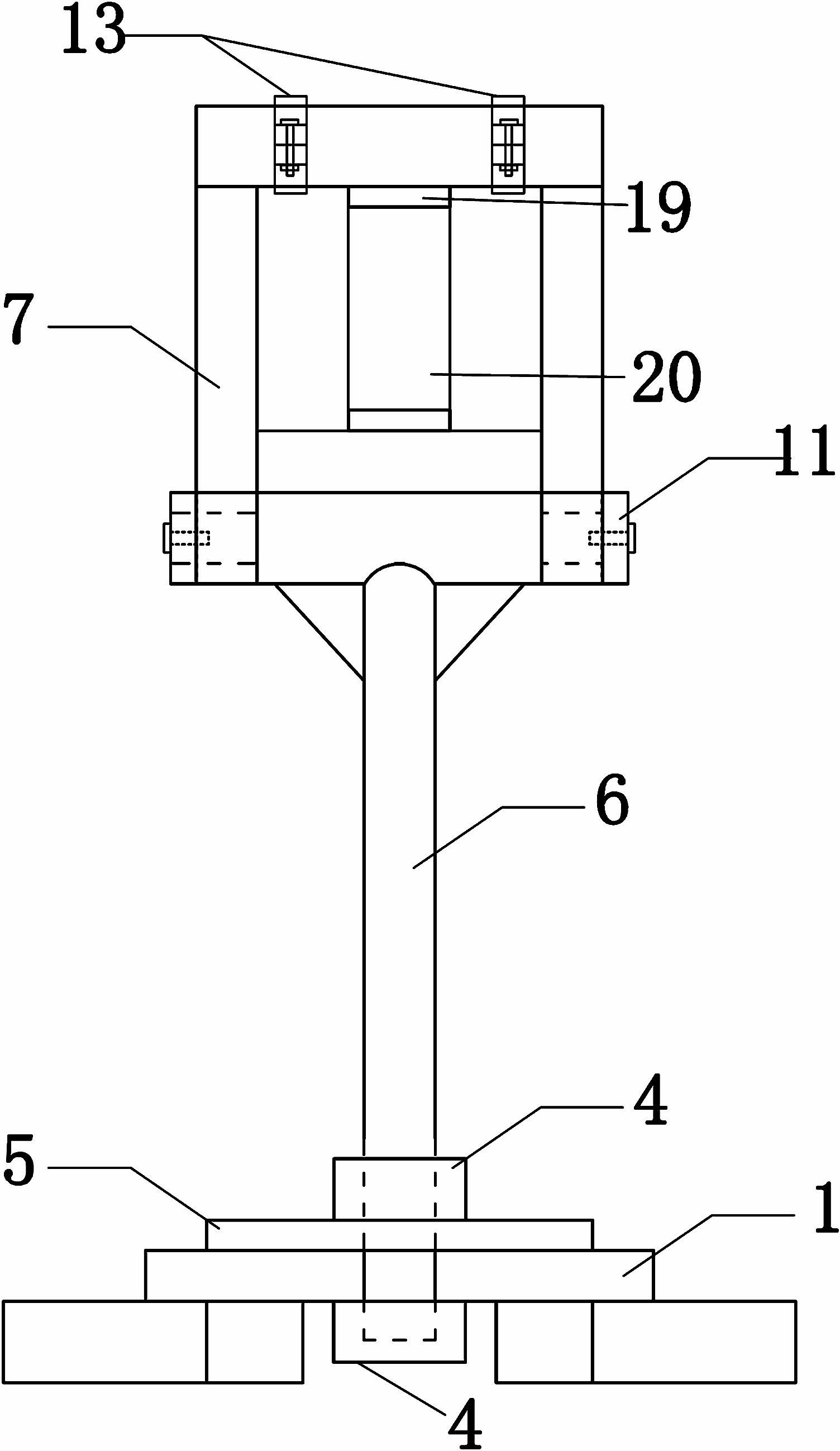
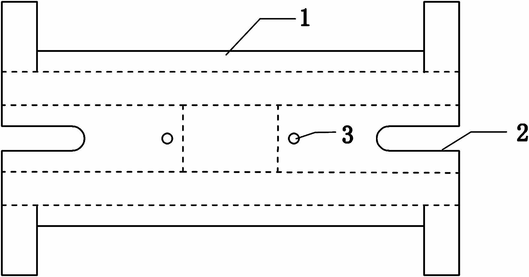
[0021] like figure 1 , image 3 Among them, a concrete beam reverse loading test device includes a base 1, chute 2 is provided at both ends of the base 1, and the support rod 6 is installed in the chute 2 through a nut 4; The nut 4 below is located in the "Ω"-shaped concave part. A reinforced backing plate 5 is also provided under the upper nut 4 to ensure that the support rod 6 is reliably stressed.

[0022] The support rod 6 is connected with the support frame 7, and the two support frames 7 are connected by a transverse tie rod 12;

[0023] like figure 1 Among them, a support rod 9 is provided on the inner side of the chute 2 on the base 1, and the support rod 9 is connected with the fixing hole 3 on the base 1 through threads, so that the height of the support rod 9 can be adjusted to suit different test pieces 20.

[0024] The support rod 9 is movably connected with the distribution beam 16 . In a preferred solution, a support groove 10 is provided at the bottom of th...


PUM


Abstract

The invention discloses a concrete beam reverse loading test device, which includes a base, wherein sliding slots are arranged at the two ends of the base; support pull rods are installed in the sliding slots through nuts, and are connected with support frames; the two support frames are connected through a transverse pull rod; supporting rods are arranged on the base and positioned on the inner sides of the sliding slots; the supporting rods are movably connected with a distribution cross beam; and a lifting jack and a force sensor are arranged below the distribution cross beam. The concrete beam reverse loading test device provided by the invention facilitates observation of the crack trend and measurement of the crack width of a test piece through adopting the reverse loading manner, so that the testing data is obtained easily; and the structure that support rotating shafts are matched with retaining rings is adopted, so that the test piece is loaded easily; and the length can be adjusted conveniently to be matched with the length of the test piece through matching the sliding slots on the base and the transverse pull rods with the retaining ring structure.

Description

technical field [0001] The invention relates to the field of concrete load experiments, in particular to a concrete beam reverse loading test device which can complete damage experiments without unloading components under long-term loads. Background technique [0002] At present, experiments to study the influence of long-term constant loads on structures are basically carried out by loading heavy objects. During the damage test, they will be unloaded first and then loaded and damaged. This is different from the actual component that is damaged under continuous load. The loaded object has a large volume and covers a large area, and it is very inconvenient to move or adjust after loading, resulting in low experimental efficiency, and there will be a certain gap between the obtained results and the actual results, which is not conducive to the study of the general failure of components under long-term loads. law. [0003] Chinese patent 201120125585.1 provides a stress static...

Claims


Application Information

Patent Timeline
Patent Type & Authority Applications(China)
IPC IPC(8): G01N3/00G01M99/00
Inventor 徐港梁桂林王青高德军郝江波
Owner CHINA THREE GORGES UNIV
Why Eureka
Try Eureka