Combine harvester

A combine harvester and fan technology, applied in agricultural machinery and implements, threshing equipment, agriculture, etc., can solve the problem that the separation device cannot be used for maximum effect, complexity, etc.

Inactive Publication Date: 2012-08-01
爱科股份公司
View PDF4 Cites 1 Cited by
  • Summary
  • Abstract
  • Description
  • Claims
  • Application Information

AI Technical Summary

Problems solved by technology

The problem is complicated by the recent development of separating devices arranged upstream capable of supplying very high crop flows
Insufficient

Method used


Image

  • Combine harvester
  • Combine harvester
  • Combine harvester

Examples


Embodiment Construction

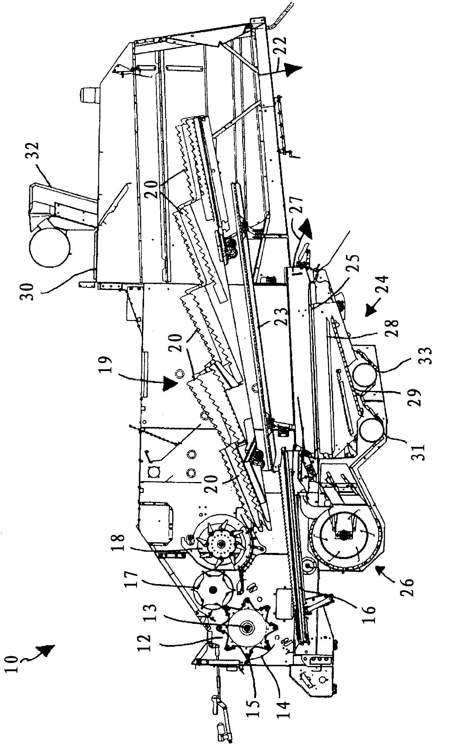
[0023] When reading the following description, it should be understood that the terms longitudinal and transverse are relative to the normal direction of travel of the combine harvester. In other words, the term portrait is equivalent to the front-rear direction, and the term landscape is equivalent to the landscape or left-right direction. Also, the terms axial and radial are relative to a rotating body such as a shaft, wherein axial is equivalent to a direction along the axis of rotation and radial is equivalent to a direction perpendicular to the axis of rotation.

[0024] refer to figure 1 , combine harvester 10 includes a header (not shown) that cuts crops as harvester 10 drives across a field. The crop is conveyed by elevators (also not shown) to the threshing drum (generally indicated at 12). The threshing drum 12 rotates on a transverse axis 13 within a drum shell 14 . Breakaway bars 15 cause the grain to be threshed from the heads of each plant and a portion of the...


PUM


Abstract

A combine harvester (10) comprising fan apparatus (26) for generating an air stream through cleaning apparatus (24) to separate chaff from grain is provided. The fan apparatus comprises a plurality of fan modules (35) for generating mutually spaced air sub-streams. The cleaning apparatus comprises an auxiliary air intake located between two adjacent air sub-streams, and means (52) to narrow the passage for each air sub-stream adjacent the auxiliary air intake (50). The narrowing serves to create a region of lower pressure (L) due to the venturi effect. The low pressure region draws air directly from the environment into the air stream through the auxiliary air intake thereby reducing the transverse component of the sub-streams and providing a more uniform air flow through the cleaning apparatus.

Description

technical field [0001] The present invention relates to a combine harvester and in particular to its grain cleaning section downstream of the threshing device. Background technique [0002] For decades, farmers have used self-propelled combines to harvest a wide range of crops, including grains, corn and canola. Typically, a combine harvester cuts the crop, threshes the grain from the crop, separates the grain from the straw, and cleans the grain before storage in an on-board storage tank. Straw and crop residues are ejected from the rear of the machine. Well setting means for cleaning grain consists of causing the grain to fall on a reciprocating screen in combination with directing air flow across the top surface of the screen. The grain passes through the sieve, while the lighter crop residues or chaff are carried away and discharged by the generally horizontal air flow. Typically, the speed of the air flow is controlled to enable the operator to expel the chaff withou...

Claims


Application Information

Patent Timeline
IPC IPC(8): A01F12/44
CPCA01F12/444
Inventor J·B·索伦森
Owner 爱科股份公司
Why Eureka
Try Eureka