End effect suppression method based on neural network ensemble and B-spline empirical mode decomposition (BS-EMD)

A neural network, endpoint effect technology, applied in the field of signal processing

Inactive Publication Date: 2012-08-08
YANSHAN UNIV
View PDF2 Cites 23 Cited by
  • Summary
  • Abstract
  • Description
  • Claims
  • Application Information

AI Technical Summary

Problems solved by technology

[0006] The problem to be solved by the present invention is to provide a method for suppressing endpoint effects based on neural network integration and BS-EMD, so as to overcome the defects of endpoint effects in the EMD process of the prior art

Method used


Image

  • End effect suppression method based on neural network ensemble and B-spline empirical mode decomposition (BS-EMD)
  • End effect suppression method based on neural network ensemble and B-spline empirical mode decomposition (BS-EMD)
  • End effect suppression method based on neural network ensemble and B-spline empirical mode decomposition (BS-EMD)

Examples


Embodiment Construction

[0055] The specific implementation manners of the present invention will be further described in detail below in conjunction with the accompanying drawings and embodiments. The following examples are used to illustrate the present invention, but are not intended to limit the scope of the present invention.

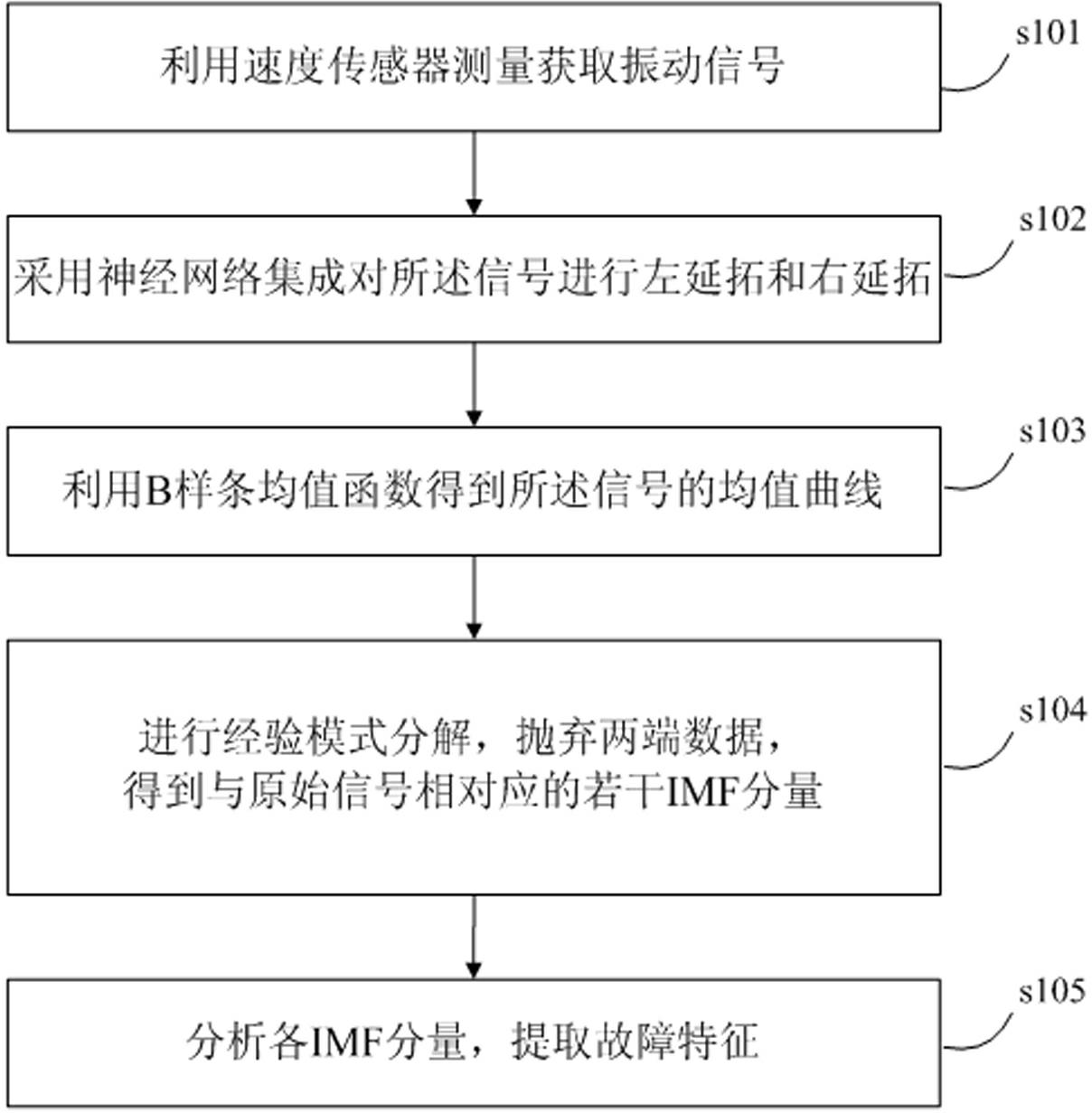
[0056] An endpoint effect suppression method based on neural network integration and BS-EMD in the embodiment of the present invention is as follows: figure 1 shown, including the following steps:

[0057] Step s101, using a speed sensor to measure and acquire a vibration signal.

[0058] Step s102, performing left extension and right extension on the signal by neural network integration. Extending the signal using neural network ensembles involves the following steps:

[0059] (1) When there is only one layer of neural network, the data sequence extension using neural network is mainly divided into two steps: learning and extension. The purpose of the neural network l...


PUM


Abstract

The invention discloses an end effect suppression method based on the neural network ensemble and B-spline empirical mode decomposition (BS-EMD). The end effect suppression method includes the steps as follows: A, vibration signals are measured and obtained by utilizing a speed sensor; B, the signals are continued leftwards and rightwards by adopting the neural network ensemble; C, a mean curve of the signals is obtained by utilizing a B-spline mean function; and D, empirical mode decomposition (EMD) is conducted, data at the two ends of the mean curve are abandoned, and a plurality of intrinsic mode function (IMF) components corresponding to original signals are obtained; and E, each IMF component is analyzed, and fault feathers are extracted. The end effect suppression method has the advantages that an end effect can be effectively suppressed, and the influence of the end effect on BS-EMD results is avoided.

Description

technical field [0001] The invention relates to the technical field of signal processing, in particular to an endpoint effect suppression method based on neural network integration and BS-EMD (B-spline empirical mode decomposition, B-spline empirical mode decomposition). Background technique [0002] Large rotating machinery is the key equipment of modern metallurgy, electric power, petroleum and other departments. Limited by the working environment and service life, some parts of the mechanical equipment are prone to some failures, which will affect the normal operation of the entire equipment, and even lead to machine crash and death, resulting in major economic losses. When the rotating machinery breaks down or is abnormal, the vibration signals are mostly nonlinear and non-stationary, and these non-stationary signals often contain a large amount of fault characteristic information. Therefore, fault diagnosis and monitoring of rotating machinery is of great significance ...

Claims


Application Information

Patent Timeline
Patent Type & Authority Applications(China)
IPC IPC(8): G06F17/14G06N3/08
Inventor 孟宗顾海燕李姗姗
Owner YANSHAN UNIV
Why Eureka
Try Eureka