

Wearable blind-guiding device based on wireless sensor network and vibration feedback
A technology of wireless sensor and vibration feedback, which is applied in the direction of devices that help people walk, physical therapy, ophthalmology treatment, etc. The effect of wearing complex problems, low power consumption, and easy wearing
- Summary
- Abstract
- Description
- Claims
- Application Information
AI Technical Summary
Problems solved by technology
Method used
Image

Examples
Embodiment Construction
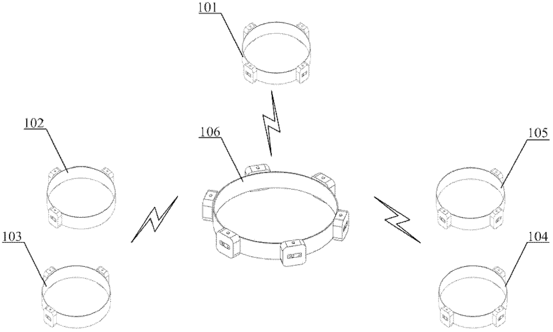
[0022] The invention is a walking assistance system for visually impaired persons, including three parts: a head detection device, a waist detection device and a leg detection device, and the three parts perform data communication through a wireless sensor network. The waist detection device is a network gateway, and the head and leg detection devices are network nodes. The head detection device mainly detects obstacles and approaching people or objects in the four directions of front, rear, left, and right; detection in two directions; the leg detection device is divided into two thigh obstacle avoidance sub-devices and two calf obstacle avoidance sub-devices, and each device can detect obstacles in three directions: front, rear and outside of the legs, so that the whole system can be used. Carry out all-round detection around the human body, and the detection is completed by distance measuring sensors.
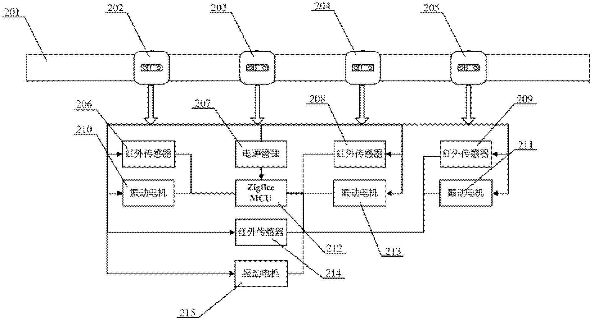
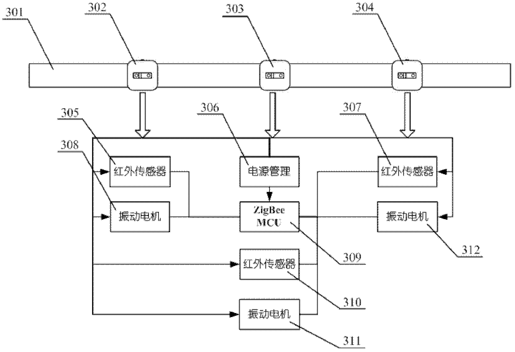
[0023] The head and leg detection device is mainly composed of four pa...
PUM
 Abstract
Description
Claims
Application Information