Cutter with extendable machining range

A processing range, cutting machine technology, applied in the direction of metal processing equipment, manufacturing tools, metal sawing equipment, etc., can solve the problems that do not meet the market demand, cannot meet the processing conditions of larger-sized workpieces, etc.

Inactive Publication Date: 2012-08-15
REXON IND CORP LTD
View PDF7 Cites 2 Cited by
  • Summary
  • Abstract
  • Description
  • Claims
  • Application Information

AI Technical Summary

Problems solved by technology

[0004] However, when the size of the workpiece is large, even if the backing plate has been moved to the end of the guide rail, it still cannot meet the lack of processing...

Method used


Image

  • Cutter with extendable machining range
  • Cutter with extendable machining range
  • Cutter with extendable machining range

Examples


Embodiment Construction

[0023] Below in conjunction with accompanying drawing and embodiment the present invention is described in detail:

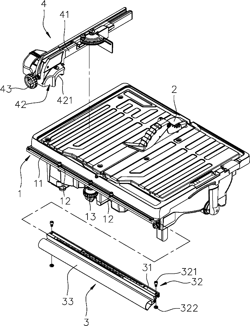
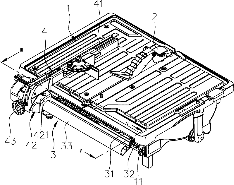
[0024] refer to figure 1 , figure 2 and image 3 , The first preferred embodiment of the cutting machine with extended processing range of the present invention includes a workbench 1 , a sawing unit 2 , a movable rail unit 3 , and a board unit 4 .

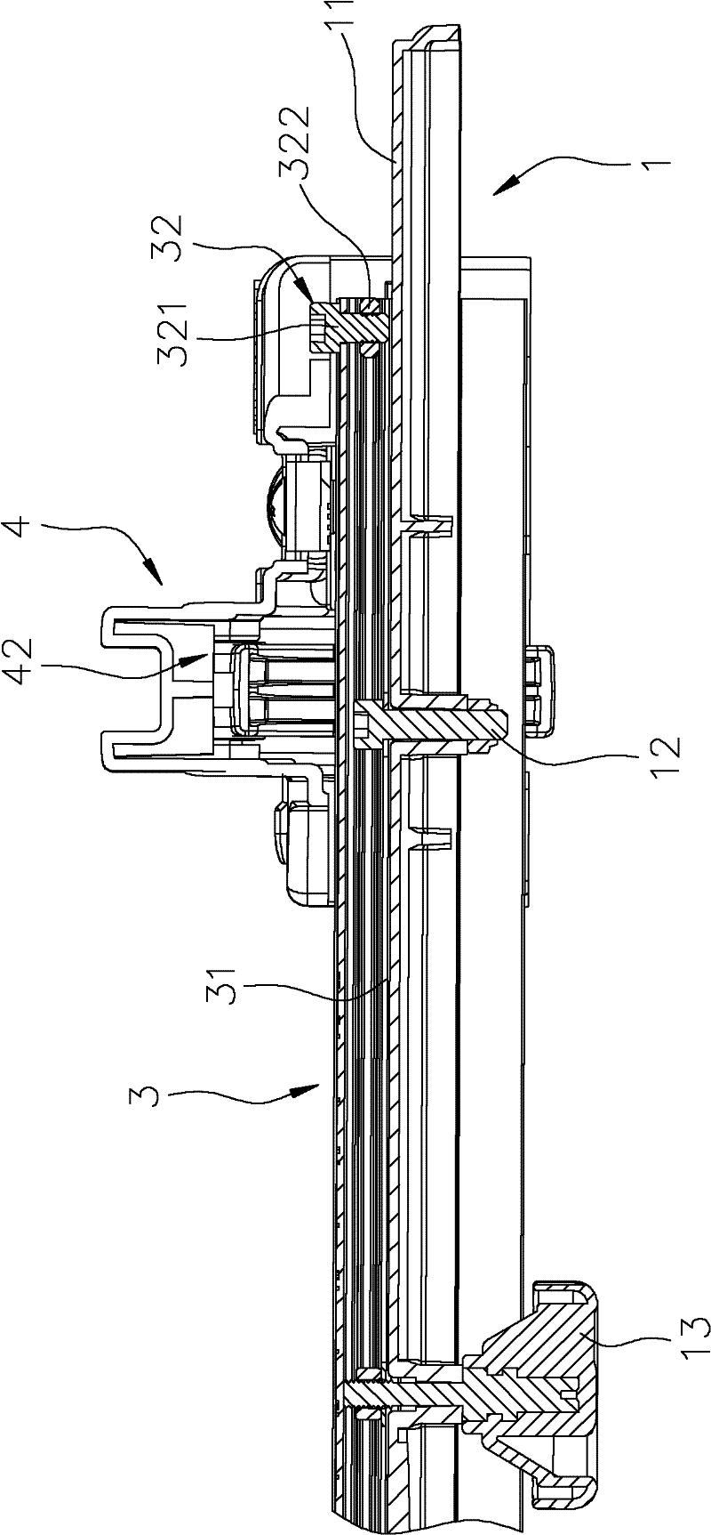
[0025] The workbench 1 includes a first guide rail 11 formed on a side edge, and the first guide rail 11 protrudes upward. The workbench 1 further includes two stop bolts 12 disposed on the first guide rail 11 and protruding upward from the channel body 31 , and a fixing member 13 disposed on the first guide rail 11 .

[0026] The sawing unit 2 is mounted on the workbench 1 .

[0027] Cooperate with reference Figure 5 , the mobile guide rail unit 3 is installed on the first guide rail 11 of the workbench 1, the mobile guide rail unit 3 includes a channel body 31 correspondingly arranged on the first guide rai...


PUM


Abstract

The invention provides a cutter with an extendable machining range. The cutter comprises an operating platform, a sawing unit, a movable type guide rail unit, a backup plate unit, and a fixing piece mounted on one of the operating platform and the movable type guide rail unit. The operating platform comprises a first guide rail; the movable type guide rail unit comprises a slot main body mounted on the first guide rail and a second guide rail; the fixing piece is abutted against the other one of the operating platform and the movable type guide rail unit, which is not provided with the fixing piece; and the backup plate unit comprises a backup plate arranged on the platform face of the operating platform, and a guide base arranged on the second guide rail. When the cutter moves relatively to the operating platform through the movable type guide rail unit, the cutter can extend outwards in a machining range, so that even if a size of the working piece is larger, a machining condition of the working piece with a larger size is met by changing a position of the movable type guide rail unit relative to the operating platform.

Description

technical field [0001] The invention relates to a cutting machine, in particular to a cutting machine with an extendable processing range. Background technique [0002] A conventional cutting machine, such as that disclosed in US Patent Application No. US2009 / 0277315A1, includes a workbench, a sawing unit, a guide rail formed on the side edge of the workbench, and a rest that slides along the guide rail. plate. [0003] When sawing the workpiece, the side of the workpiece is pressed against the backing plate, and then the workpiece is pushed along the backing plate to the sawing unit for processing. When the workpieces are of different sizes, the backing plate The relative distance to the sawing unit is adjusted along the guide rail to meet the processing conditions of workpieces of different sizes. [0004] However, when the size of the workpiece is large, even if the backing plate has been moved to the end of the guide rail, it still cannot meet the lack of processing co...

Claims


Application Information

Patent Timeline
IPC IPC(8): B23D47/00
Inventor 郑志明
Owner REXON IND CORP LTD
Why Eureka
Try Eureka