
Hydraulic press machine of jack

A jack and press technology, applied in the field of press machinery, can solve the problem of inconvenient placement of fasteners, etc., and achieve the effect of enhancing convenience and preventing loss

Inactive Publication Date: 2012-08-15
CHANGSHU TONGRUN AUTO ACCESSORY
View PDF10 Cites 5 Cited by
  • Summary
  • Abstract
  • Description
  • Claims
  • Application Information

AI Technical Summary

Problems solved by technology

[0005] But, above-mentioned patent and patent application scheme still exist the tool such as wrench, screwdriver, pliers and so on that are not convenient for placing operation and place fastener such as screw, nut etc., so there is still a need for improvement. The technical solution to be introduced below is based on this premise.

Method used


Image

  • Hydraulic press machine of jack
  • Hydraulic press machine of jack

Examples


Embodiment 1

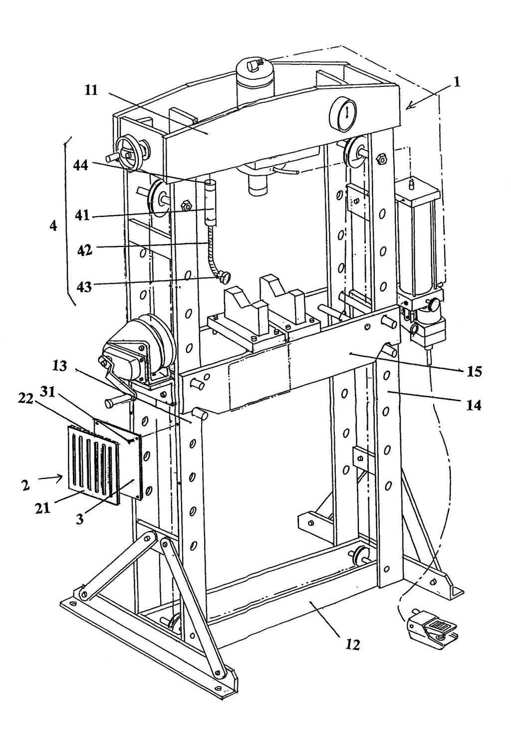
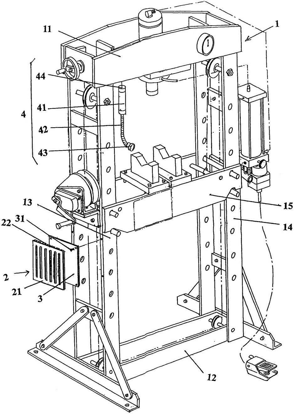
[0020] please see figure 1 , the given frame 1 is composed of upper and lower beams 11, 12, first and second longitudinal arms 13, 14 and workpiece racks 15 connected between the upper and lower beams 11, 12 and kept parallel to each other up and down, Wherein, the workpiece holder 15 can be adjusted on the first and second longitudinal arms 13, 14, so as to meet the required height requirement.

[0021] As the technical points of the technical solution provided by the present invention: a tool suction mechanism 2 is arranged on the aforementioned first longitudinal arm 13, and the tool suction mechanism 2 includes a magnetically conductive metal plate 21 and a magnet 22, and the magnet 22 is connected to the first longitudinal The arm 13 is attracted, and the magnetically permeable metal plate 21 is attracted to the magnet 22 .

[0022] As a preferred solution, in this embodiment, a magnetically permeable seat plate 3 is fixed on the first longitudinal arm 13 through ...

Embodiment 2

[0026] The diagram is omitted, only the tool suction mechanism 2 is transferred to the aforementioned second longitudinal arm 14, and the magnet 22 is replaced with a whole magnetic plate, and the magnetic plate is attracted to the second longitudinal arm 14 for magnetic conduction. The metal plate 21 is attracted to the magnetic plate, and the magnetic base plate 3 of the first embodiment can be omitted in this embodiment, and the rest are the same as the description of the first embodiment.

Embodiment 3

[0028] The figure is omitted, the tool suction mechanism 2 is arranged on the aforementioned workpiece frame 15, and the magnet 22 is replaced with a plurality of magnetic blocks arranged at intervals from each other. Combined on the magnetic block, all the other are the same as the description of embodiment 1.


PUM


Abstract

The invention relates to a hydraulic press machine of a jack and belongs to the technical field of press machinery. The hydraulic press machine comprises a machine frame, wherein the machine frame consists of an upper cross beam, a lower cross beam, a first longitudinal arm, a second longitudinal arm and a workpeice frame, the first longitudinal arm and the second longitudinal arm are connected between the upper cross beam and the upper cross beam and are mutually parallel, the workpiece frame is connected with the first longitudinal arm, the second longitudinal arm and is positioned between the upper cross beam and the lower cross beam. The hydraulic press machine is characterized by also comprising a tool suction mechanism, wherein the tool suction mechanism is arranged on the first longitudinal arm, the second longitudinal arm or the workpiece frame. The hydraulic press machine has the advantages that the tool suction mechanism is arranged on the first longitudinal arm, the second longitudinal arm or the workpiece frame, so operators can conveniently deposit tools such as spanners, tongs, mallets and hammers, and fastening elements such as screws, screw nuts, and gaskets on the tool suction mechanism in a magnetic suction mode, the operation convenience is favorably enhanced, and the tools and / or the fastening elements are also favorably prevented from being lost.

Description

technical field [0001] The invention belongs to the technical field of pressure machinery, and in particular relates to a jack hydraulic press. Background technique [0002] As is well known in the industry, compared with the dedicated large and medium-sized hydraulic presses, jack hydraulic presses can play a role in supplementing gaps. The specific performances are strong adaptability, small size, simple operation and low investment. Production lines, construction sites waiting for work, repair sites in the electromechanical maintenance industry, vehicles such as maintenance departments of various vehicles, and can be applied to homes, etc. [0003] Jack hydraulic presses have been reported in documents, especially Chinese patent documents, such as utility model authorization announcement number CN201205566Y (jack hydraulic press), CN2144571Y (manual hydraulic press), and CN201385455Y (manual screw with additional jack-type layer). press), etc. [0004] The deficiencies ...

Claims


Application Information

Patent Timeline
IPC IPC(8): B30B1/32B30B15/00
Inventor 李萍唐洁石永良刘羽
Owner CHANGSHU TONGRUN AUTO ACCESSORY
Learn More