Reinforced concrete laminated slab

A technology of reinforced concrete and laminated slabs, applied in the direction of floor slabs, structural elements, building components, etc., can solve the problems of high cost, joint surface cannot be equal to cast-in-place, inconvenient prefabricated slab production and construction, etc. The effect of shear performance

Inactive Publication Date: 2012-08-15
CHINA MCC17 GRP
View PDF5 Cites 4 Cited by
  • Summary
  • Abstract
  • Description
  • Claims
  • Application Information

AI Technical Summary

Problems solved by technology

At present, in the design of laminated slabs, the joint surface cannot be equivalent to cast-in-place, and some prefabricated slabs are inconvenient to manufacture and construct, and even the cost is relatively high

Method used


Image

  • Reinforced concrete laminated slab
  • Reinforced concrete laminated slab

Examples


Embodiment Construction

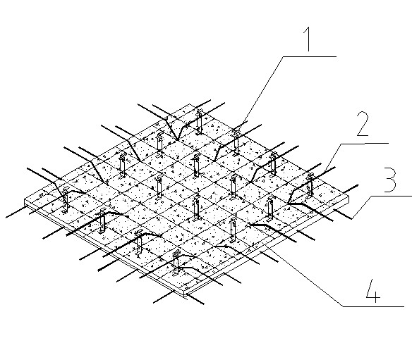
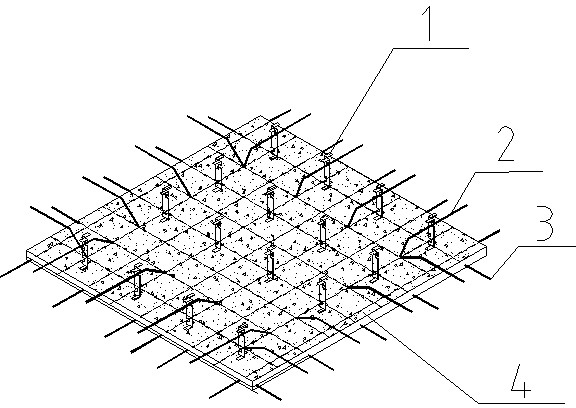
[0008] The reinforced concrete composite slab of the present invention will be further described below in conjunction with the accompanying drawings.

[0009] from figure 1 It can be seen that the reinforced concrete composite slab is composed of the bottom steel bar 3, the bent steel bar 2, the limiter 1 and the prefabricated layer 4. It is composed of a connecting body between the upper limit surface and the lower limit surface. The lower limit surface of the stopper is located in the prefabricated layer 4. The thickness of the laminated plate is controlled by the distance between the upper limit surface and the lower limit surface of the stopper 1. Half of the bent steel bar 2 is set in the prefabricated layer 3 to strengthen the connection between the cast-in-place layer and the prefabricated layer.

[0010] The invention fully considers the stress characteristics of the slab, fully utilizes the function of the material, and ensures that the joint surfaces of the prefabri...


PUM


Abstract

The invention discloses a reinforced concrete laminated slab consisting of plate bottom steel bars, bent-up steel bars, limiting stoppers and a prefabrication layer. The reinforced-concrete laminated slab is characterized in that each limiting stopper is I-shaped and consists of an upper limiting surface, a lower limiting surface and a connector between the upper and lower limiting surfaces, the lower limiting surfaces of the limiting stoppers are positioned in the prefabrication layer, and the half parts of the bent-up steel bars are arranged in the prefabrication layer. As the laminated slab fully utilizes the functions of materials, the common stress on an adjoining face between the prefabrication layer and a cast-in-situ layer of the laminated slab is ensured, and the shearing performance of the part of the laminated slab, close to a support, is improved.

Description

technical field [0001] The invention relates to the technical field of building structural parts, in particular to a reinforced concrete composite slab. Background technique [0002] As a part of the laminated structure, the reinforced concrete laminated slab is a structural form combining prefabrication and cast-in-place. During the construction process of the composite slab, the prefabricated bottom slab is first placed at the bottom, which acts as a formwork when pouring the upper concrete, and then the two parts of concrete form a whole to bear the load. At present, in the design of laminated slabs, the joint surface cannot be equivalent to cast-in-situ, and some prefabricated slabs are inconvenient to manufacture and construct, and even the cost is relatively high. The present invention preferably solves these problems. Contents of the invention [0003] The purpose of the patent of the present invention is to provide a reinforced concrete laminated slab, which over...

Claims


Application Information

Patent Timeline
IPC IPC(8): E04B5/17E04C5/16
Inventor 刘守城刘运林尹万云丁克伟何兆芳
Owner CHINA MCC17 GRP
Why Eureka
Try Eureka