Method for running bridge plug sitting tool by means of differential pressure and bridge plug sitting tool utilized by same

A bridge plug seat and tool seat technology, which is applied in the field of bridge plug seat sealing tools, can solve the problems of damage to perforating equipment, large vibration, etc., and achieve the effects of overcoming large vibration, convenient operation, and simple tool structure

Active Publication Date: 2012-08-15
CHINA PETROLEUM & CHEM CORP +1
View PDF10 Cites 18 Cited by
  • Summary
  • Abstract
  • Description
  • Claims
  • Application Information

AI Technical Summary

Problems solved by technology

[0003] The traditional cable bridge plug seat seal adopts electric ignition, and the gunpowder deflagrates in the seat seal tool to generate high-pressure gas as the power of the seat seal bridge plug, which has the following disadvantages: large vibration; when the bridge plug operation is combined with perforation, it may be damaged Perforating equipment; involving the use of pyrotechnics, there is a certain degree of danger

Method used


Image

  • Method for running bridge plug sitting tool by means of differential pressure and bridge plug sitting tool utilized by same
  • Method for running bridge plug sitting tool by means of differential pressure and bridge plug sitting tool utilized by same
  • Method for running bridge plug sitting tool by means of differential pressure and bridge plug sitting tool utilized by same

Examples


Embodiment Construction

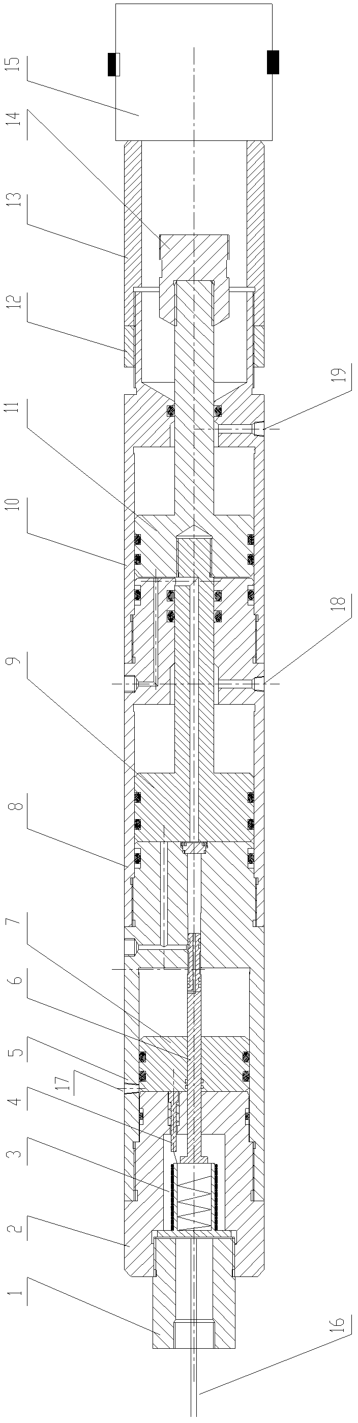
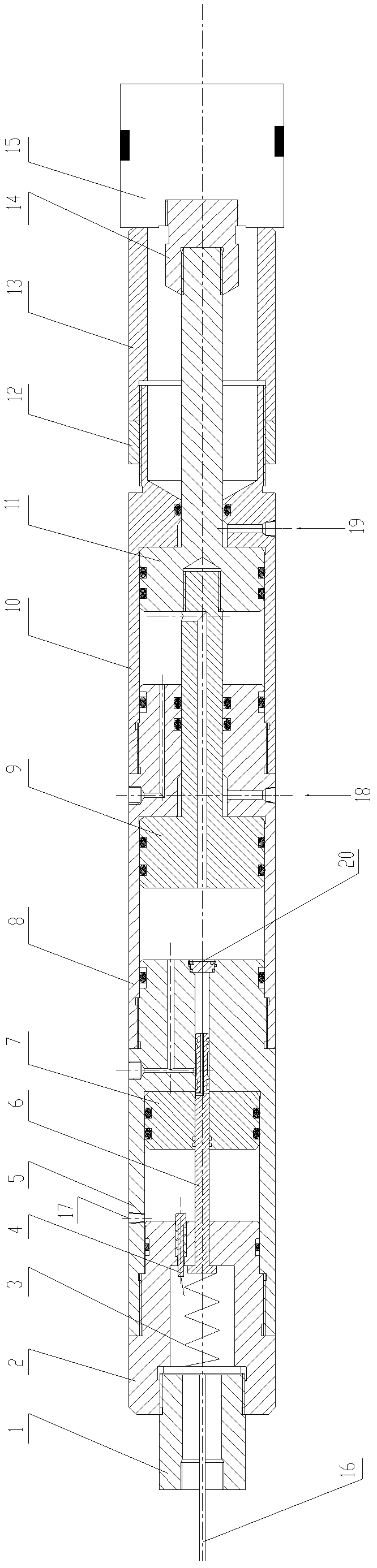
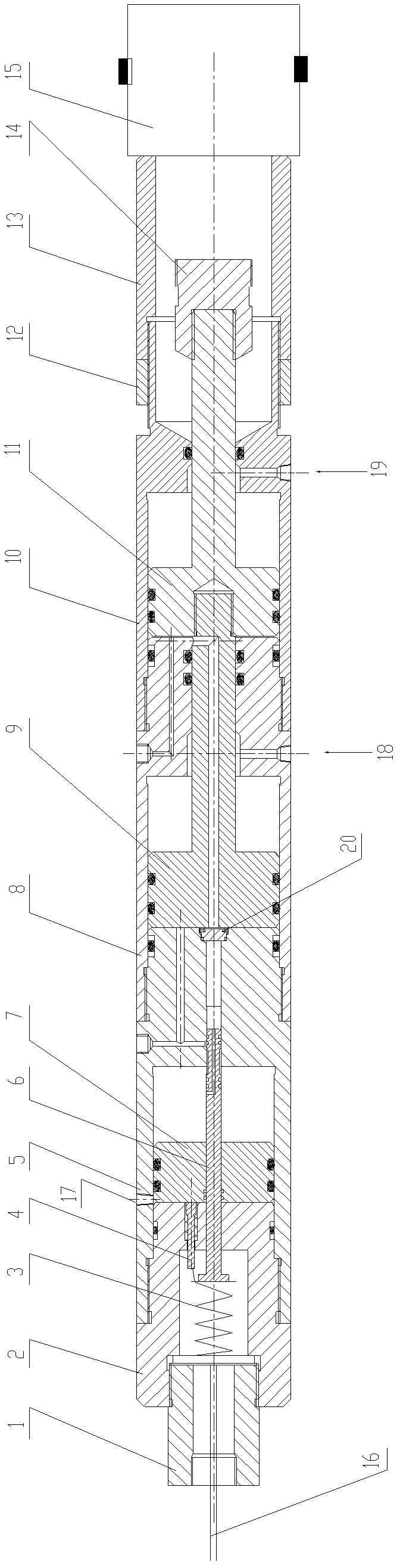
[0023] The method of using the pressure difference to use the bridge plug setting tool to set the seal, the specific steps are as follows:

[0024] 1) Open the oil cavity channel of the bridge plug seating tool, and the annular liquid enters the middle outer cylinder and the lower outer cylinder of the bridge plug seating tool from the liquid inlet of the bridge plug seating tool,

[0025] 2) The pressure difference between the incoming liquid and the air chamber drives the piston upward, and the upward movement of the piston drives the bridge plug connector to move upward. The bridge plug connector is connected to the center rod of the bridge plug, and the bridge plug center rod moves upward to compress the bridge plug seat seal. pieces to seal the bridge plug,

[0026] 3) After the bridge plug is seated, the piston continues to move upward until the bridge plug connection joint is separated from the center rod of the bridge plug, and the bridge plug is dropped.

[0027] 4) ...


PUM


Abstract

The invention relates to a method for running a bridge plug sitting tool by means of differential pressure and a bridge plug sitting tool used by the same. When a bridge plug is sit, the bridge plug is electrified from the ground through a cable, an electromagnetic valve is turned on or a rupture disk is ruptured, a liquid inlet hole is opened, or a clock is turned on to drive an upper mandrel to move, annulus fluid enters into the tool to drive a piston to move upwards due to the differential pressure with an air chamber, the bridge plug is sit, and the piston moves continuously and upwards so as to be released from the bridge plug. The bridge plug sitting tool has three types such as an electromagnetic valve control type, a rupture disk control type and a clock control type, and consists of a cable connecting joint, an upper joint, an upper outer cylinder, a middle outer cylinder, a lower outer cylinder, an adjusting nut, a push rod, one bridge plug connecting joint, an internally-arranged electromagnetic valve, an internally-arranged contact switch, an upper mandrel, a piston, an upper piston rod, a lower piston rod, another bridge plug connecting joint and the like which are in threaded connection with one another. According to the invention, the bridge plug is stable in sitting process, and small in vibration, and when the bridge plug is connected with a perforation hole in parallel, a perforation apparatus can not be vibrated to be broken; and when the bridge plug is released, the contact switch can be touched, so that a conducting wire is disconnected, and the tool provided by the invention is obvious in ground display.

Description

technical field [0001] The patent of the present invention relates to a method for lowering a bridge plug for oil and water wells and a used bridge plug setting tool. In particular, solenoid valve controlled, rupture disk controlled, clock controlled hydraulic seating methods and seating tools. Background technique [0002] Bridge plugs are used to seal oil and gas wells. They have the characteristics of less construction procedures, short periods, and accurate sealing positions. They are divided into permanent bridge plugs and removable bridge plugs. Its working principle is: use cables or pipe strings to transport it to the predetermined position in the wellbore, the pressure generated by gunpowder blasting, hydraulic seating or mechanical seating tools acts on the upper slips, the pulling force acts on the tension rods, and the upper and lower cones exert pressure on the tension rods. The sealing rubber cylinder is applied with two forces of above pressure and pulling. W...

Claims


Application Information

Patent Timeline
Patent Type & Authority Applications(China)
IPC IPC(8): E21B33/134
Inventor 何开平张国锋袁发勇石陈梅
Owner CHINA PETROLEUM & CHEM CORP
Why Eureka
Try Eureka