Hinge device and portable terminal

A hinge device and a technology for specifying positions, which are applied in the field of hinge devices and portable terminals, can solve problems such as unsmooth movements, and achieve smooth and stable movements

Active Publication Date: 2012-08-15
LENOVO (BEIJING) CO LTD
View PDF7 Cites 11 Cited by
  • Summary
  • Abstract
  • Description
  • Claims
  • Application Information

AI Technical Summary

Problems solved by technology

However, the biaxial hinge structure can only realize 180-degree opening and closing, and the movement is not smooth

Method used


Image

  • Hinge device and portable terminal
  • Hinge device and portable terminal
  • Hinge device and portable terminal

Examples


no. 1 approach

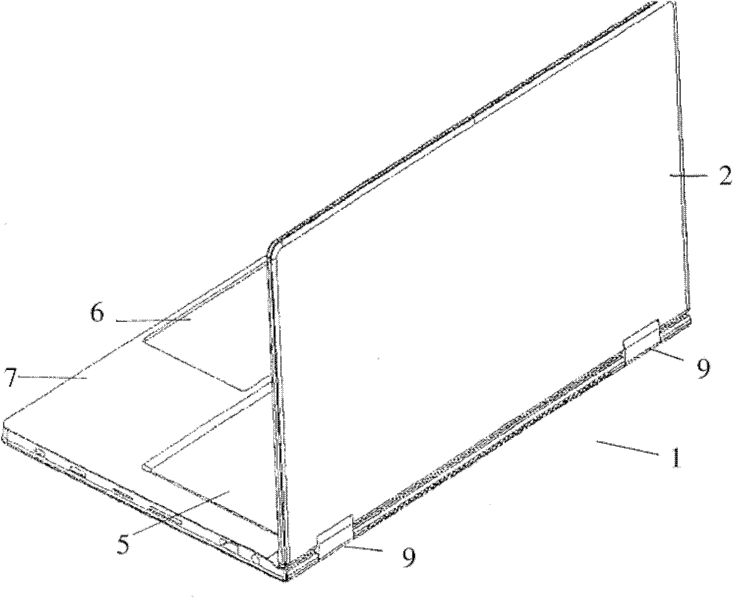
[0087] figure 1 It is a perspective view showing the appearance of the notebook computer 1 .

[0088] The notebook computer 1 is composed of a main body 7 having a key arrangement surface 5 on which input keys and the like are arranged and a touchpad 6 , and a cover 2 having a display surface (not shown) on which a liquid crystal panel and the like are arranged. The cover 2 and the main body 7 are foldably and openably connected by the hinge device 9 from a closed state in which the key arrangement surface 6 and the display surface overlap each other to an unfolded state in which it is rotated 360 degrees and opened.

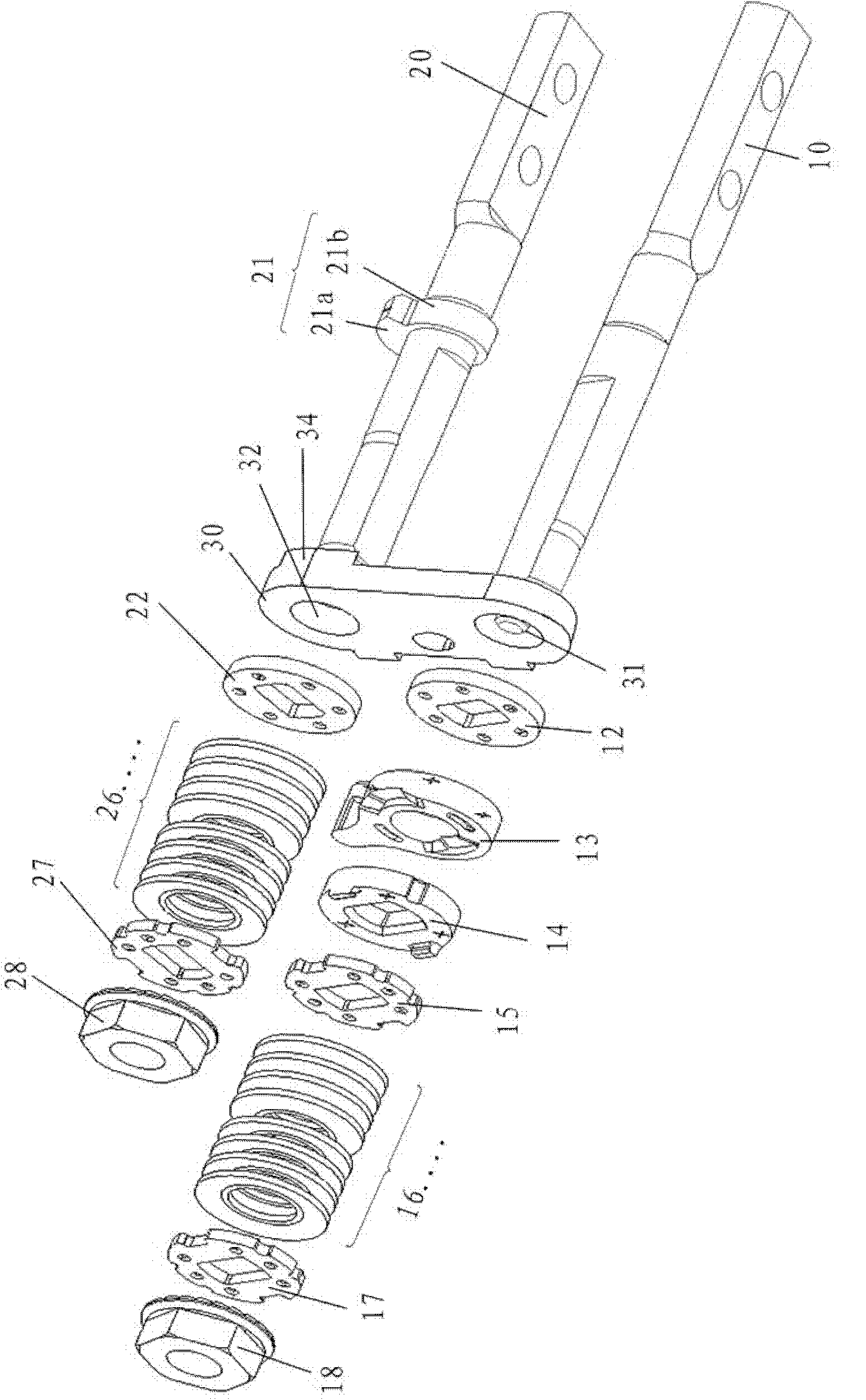
[0089] figure 2 It is a perspective view showing the hinge device 9 according to the first embodiment of the present invention in a state where the case is removed, image 3 and Figure 4 It is an exploded perspective view showing the hinge device 9 according to the first embodiment of the present invention.

[0090] The hinge device 9 is constituted as a b...

no. 2 approach

[0109] Below, refer to Figure 7 , Figure 8 A hinge device according to a second embodiment of the present invention will be described. Figure 7 is an exploded perspective view of a schematic configuration of a hinge device according to a second embodiment of the present invention, Figure 8 It is a figure which shows the arrangement|positioning of the stopper on the bracket plate used for the hinge apparatus of the 2nd Embodiment of this invention.

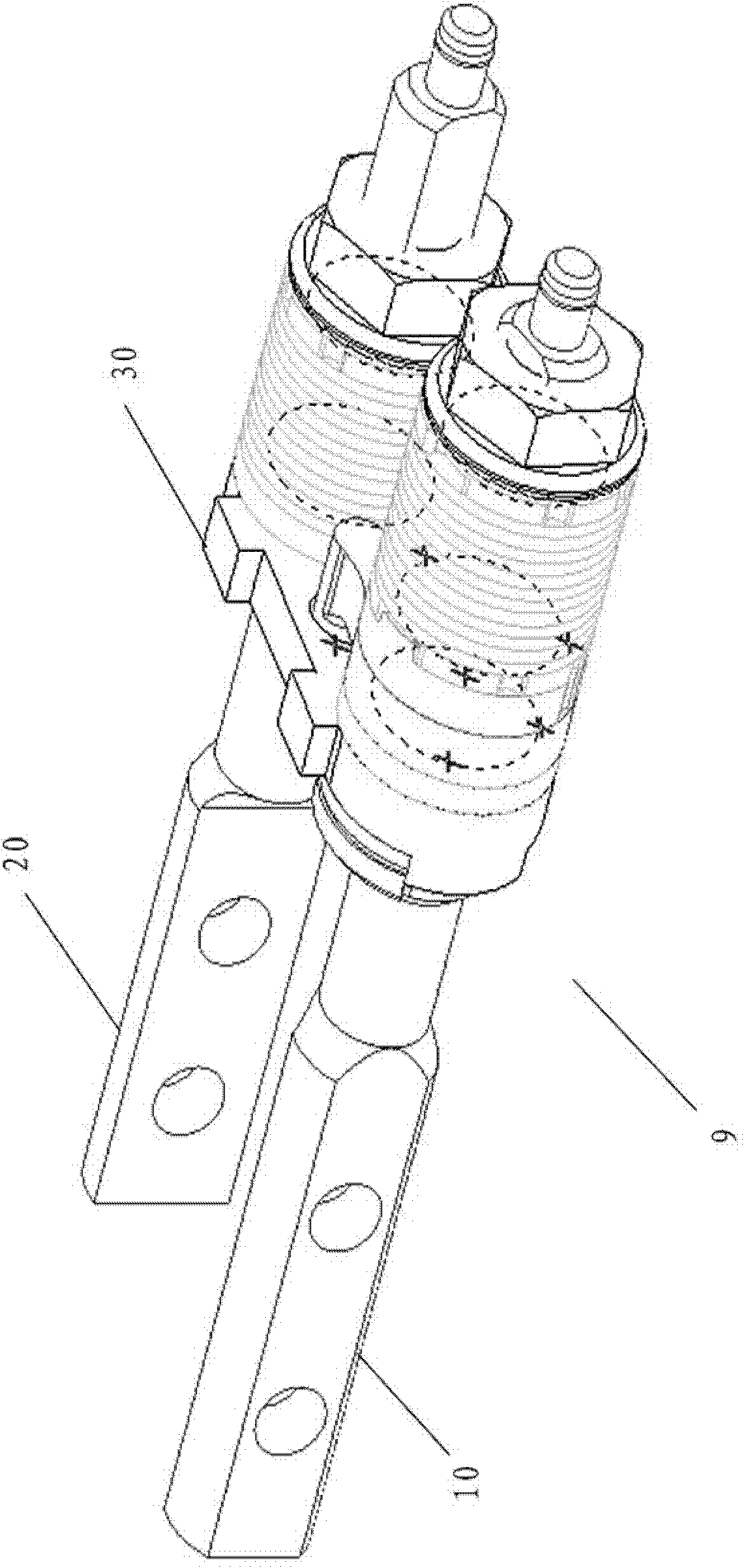
[0110] The difference between the hinge device of the second embodiment and the hinge device of the first embodiment is that a stopper 11 is provided on the first rotation center shaft 10 , and a stopper 11 is provided on the bracket plate 20 to abut against the stopper 11 . The block 33. The rest of the structure is basically the same as that of the hinge device of the first embodiment, and the same members are assigned the same symbols and detailed description thereof will be omitted.

[0111] The stopper 11 of the first ...

no. 3 approach

[0120] Below, refer to Figure 9 and Figure 10 A hinge device according to a third embodiment of the present invention will be described. Figure 9 is a schematic diagram of the structure of the hinge device according to the third embodiment of the present invention, Figure 10 It is a diagram showing the arrangement of the stopper on the bracket plate used in the hinge device according to the third embodiment of the present invention.

[0121] The difference between the hinge device of the third embodiment and the hinge device of the second embodiment is that a cam engaging part 23 and a cam 24 are provided on the second rotation center shaft 20 , and a fixed cam engaging part is provided on the bracket plate 30 . The fixing hole 36 of the part 23. In addition, the engagement arrangement of the cam 14 and the cam engagement portion 13 of the first rotation center shaft 10 and the installation positions of the stoppers 34 and 35 of the bracket plate 30 are different from t...


PUM


Abstract

The invention provides a hinge device and a portable terminal, wherein the hinge device is capable of opening and closing 360 degrees stably and smoothly. The hinge device comprises a first rotating central shaft and a second rotating central shaft, support plates, cams, cam engaging parts, press force applying devices, stopping parts and stopping blocks. The first rotating central shaft and the second rotating central shaft are supported by shafts in a mutually parallel manner, the first rotating central shaft and the second rotating central shaft are arranged on the support plates and are enabled to rotate optionally, the cams and the cam engaging parts are arranged on the first rotating central shaft and are applied with force by the press force applying devices, the stopping parts are arranged on and rotate with the second rotating central shaft integrally, and the stopping blocks are arranged on assigned positions of the support plates and correspond to the stopping parts of the second rotating central shaft. The stopping parts of the second rotating central shaft are enabled to abut against the stopping blocks to limit the rotating angle of the second rotating central shaft. When the hinge device is in action, the second rotating central shaft stops rotating if the stopping parts of the second rotating central shaft abut against the stopping blocks, and the first rotating central shaft responds to further-applied acting force to start rotating.

Description

technical field [0001] The present invention relates to a hinge device for a portable terminal such as a notebook computer in which two housings are expandably and closedly connected in a layout, and a portable terminal having the hinge device. Background technique [0002] At present, in portable terminals such as notebook computers, so-called clamshell hinge devices that can be folded and opened and closed are often used, that is, a cover portion having a display portion and a main body portion having a key operation portion are connected in a foldable manner. [0003] As such a clamshell hinge device used in a portable terminal, various structures have been proposed in recent years. Patent Document 1 proposes a biaxial hinge structure in which a linking belt such as a rope is connected to one hinge body, and after connecting the two shafts, it is connected to the other hinge body so that the biaxial hinge rotates in the opposite direction. linked in a way. However, the ...

Claims


Application Information

Patent Timeline
Patent Type & Authority Applications(China)
IPC IPC(8): F16C11/10H04M1/02G06F1/16
Inventor 侯文林代皇杨大业
Owner LENOVO (BEIJING) CO LTD
Why Eureka
Try Eureka