Compressive stress loading and deformation measurement device and measurement method for deformation of test piece under compressive stress

A measuring device and compressive stress technology, which is applied in the direction of measuring the deformation of mechanical solids and using stable tension/pressure to test the strength of materials, etc., can solve the problems of not being able to realize the measurement of deformation loading devices, etc., to facilitate analysis and research, and function Variety and accurate test results

Active Publication Date: 2012-08-15
CHINA BUILDING MATERIALS ACAD
View PDF6 Cites 13 Cited by
  • Summary
  • Abstract
  • Description
  • Claims
  • Application Information

AI Technical Summary

Problems solved by technology

[0004] In addition, the current loading device mainly focuses on realizing the convenient operation of the loading device, reducing stress relaxation, increasing stability, saving equipment investment and reduci

Method used


Image

  • Compressive stress loading and deformation measurement device and measurement method for deformation of test piece under compressive stress
  • Compressive stress loading and deformation measurement device and measurement method for deformation of test piece under compressive stress
  • Compressive stress loading and deformation measurement device and measurement method for deformation of test piece under compressive stress

Examples


Embodiment 1

[0039] A typical operation process is as follows:

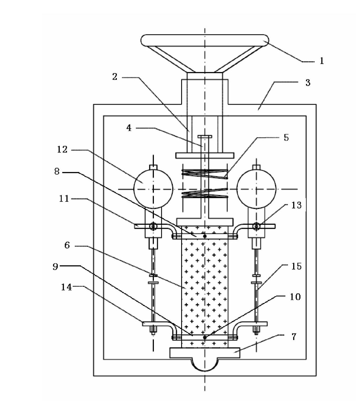
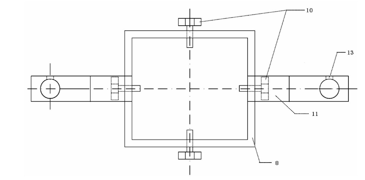
[0040] The first step: set the upper fixture 8 on the upper part of the test piece 6, fix it on the test piece 6 with four positioning bolts 10, and keep the upper fixture 8 perpendicular to the test piece 6; set the lower fixture 9 on the test piece 6 At the lower end, tighten the positioning bolt 10, and keep the lower fixture 9 perpendicular to the test piece 6.

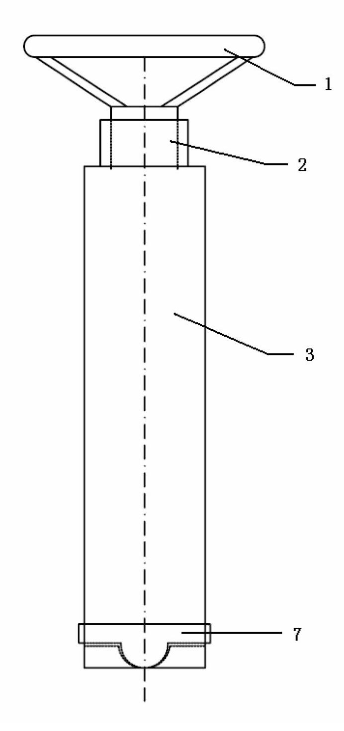
[0041] The second step: place the hemispherical end of the pressure joint 7 in the hemispherical concave shape of the frame 3, place the test piece 6 that has completed the first step on the pressure joint 7, and place the bottom end of the slide bar 4 on the flat plate Facing the test piece 6, rotate the handwheel 1 to compress the compression spring 5 to ensure that the centerlines of the slide bar 4, the test piece 6 and the pressure joint 7 coincide as much as possible, and continue to rotate the handwheel 1 to compress the compression spring 5 to the set val...

Embodiment 2

[0044] Place the test piece 6 that has completed Example 1 together with the loading device under the environmental effects of corrosive solution, dry-wet cycle, water dissolution, carbonization, etc., and coat the lower clamp 9, the adjusting bolt 15, and the measuring head of the dial indicator 12. Put vaseline on it to keep it from corroding. At this point, the deformation of the specimen under the coupling effect of compressive stress and environment can be measured.


PUM


Abstract

The invention relates to a compressive stress loading and deformation measurement device, which comprises a hand wheel with a screw rod, wherein the screw rod is rotatablely connected to a frame; the bottom end of the screw rod is connected with a fine sliding rod; a corrected compression spring is sleeved on the sliding rod; the bottom end of the sliding rod is provided with a flat plate; the flat plate is in direct contact with the top of a test piece; the test piece is vertically placed in the frame and the bottom is adhered to the top end of a bearing joint; the bearing joint is horizontally arranged in the frame; an upper clamp and a lower clamp are fixedly sleeved on the upper end and the lower end of the test piece respectively; the upper clamp and the lower clamp are provided with a dial indicator and an adjusting bolt respectively; and the adjusting bolt is kept in good contact with a measuring head at the bottom of the dial indicator. According to the device, compressive stress can be output through the compression spring, and a stress value is obtained through spring compression. The deformation can be measured by the dial indicator, the size of stress relaxation and the influence of an environmental effect on the endurance capacity of the test piece can be accurately analyzed.

Description

technical field [0001] The invention relates to the research and test of the durability performance of block building materials, in particular to a loading device capable of loading compressive stress and measuring deformation. The device is suitable for studying the damage law and degradation mechanism of durability performance of grout, mortar, concrete or other massive building materials under the coupled action of load and environmental factors. Background technique [0002] The durability of concrete is closely related to its service life. Practice has proved that the degradation of concrete durability is the result of the coupling of load and environmental factors. Therefore, it is necessary to establish experimental conditions for simulating the coupling of load and environmental factors, and to study the damage law and degradation of the durability of concrete and its raw materials under load and environmental factors. It has very important social and economic signi...

Claims


Application Information

Patent Timeline
IPC IPC(8): G01N3/14G01B5/30
Inventor 姚燕王阵地王玲
Owner CHINA BUILDING MATERIALS ACAD
Why Eureka
Try Eureka