Eureka AIR delivers breakthrough ideas for toughest innovation challenges, trusted by R&D personnel around the world.

Method for obtaining energy efficiency of main electromechanical driving system in machining process of numerically-controlled machine tool

A main drive system, CNC machine tool technology, applied in general control systems, control/regulation systems, digital control and other directions, can solve the problems of difficult on-site energy efficiency, difficult on-site model parameters, difficult to obtain on-site production, etc., and achieve online detection process. Simple and easy to operate, broad application prospects, and the effect of improving operability

Active Publication Date: 2013-11-13
CHONGQING UNIV
View PDF2 Cites 2 Cited by
  • Summary
  • Abstract
  • Description
  • Claims
  • Application Information

AI Technical Summary

Problems solved by technology

Although the existing literature has done a lot of research on the energy efficiency of machine tools, the problem of obtaining energy efficiency in the service process of machine tools at the production site has not been well solved, and there is no convenient and practical effective method
There are two main reasons for this: first, some test data needed are easy to obtain in the laboratory, but very difficult to obtain on the production site; second, the energy flow process of the main drive system of the machine tool is complicated, and it is difficult to determine the parameters of the on-site model, so the on-site energy efficiency is difficult to obtain through the model. Solve to get

Method used


Image

  • Method for obtaining energy efficiency of main electromechanical driving system in machining process of numerically-controlled machine tool
  • Method for obtaining energy efficiency of main electromechanical driving system in machining process of numerically-controlled machine tool
  • Method for obtaining energy efficiency of main electromechanical driving system in machining process of numerically-controlled machine tool

Examples


Embodiment

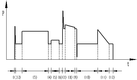
[0080] Using the model based on input power (Ⅱ) to process a certain shaft part (the shape and size of the part is as follows figure 1 The energy efficiency of the main drive system in the machining process is measured and calculated. The power sensor EDA9033A used to measure the input power is installed at the entrance of the main motor, and the data sampling period is 20ms. At the same time, the actual energy efficiency is obtained through the torque sensor TQ201 installed in the cutting area and the watt-hour meter installed at the entrance of the main drive system to provide accuracy verification.

[0081] Table 3 C2-6136HK / 1 CNC lathe parameters

[0082]

[0083] 1-1) Acquisition of basic functions and basic coefficients

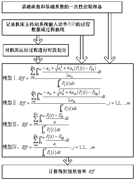
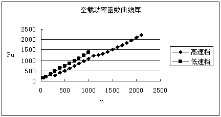
[0084] As mentioned above, to apply model (II) to obtain the energy efficiency of machine tools, the basic functions and basic coefficients that need to be prepared include the no-load power function and load loss factor table functions .

[0...


PUM


Abstract

The invention discloses a new method for obtaining energy efficiency of a main electromechanical driving system in a machining process of a numerically-controlled machine tool. In the method, according to an energy efficiency mathematical model of the main electromechanical driving system in the machining process of a machine tool, a relation function of no-load power of the machine tool which is prepared in advance stage at one time and the rotating speed and a table function of an additional load loss factor of the machine tool with single-interval or multi-interval rotation speed, as long as input power process data or process curve of a motor of the main driving system of the machine tool in the machining process is recorded, the energy efficiency of the main electromechanical driving system in the machining process of the machine tool can be calculated out from the mathematical model. The method can be used for research and application of solution to a series of problems, such as research on energy consumption and energy efficiency and evaluation on energy efficiency in the machining process of the machine tool, and energy-saving optimization of cutting technology parameters, thereby having extensive application prospect.

Description

technical field [0001] The invention belongs to the technical field of machine tool control, and in particular relates to a new method for obtaining the energy efficiency of an electromechanical main transmission system in the machining process of a numerically controlled machine tool. Background technique [0002] The energy consumption state analysis and energy efficiency evaluation of manufacturing system are the basis of reducing energy consumption and improving energy efficiency of manufacturing system. For this reason, the research on energy efficiency assessment of manufacturing system is rapidly rising in the world. CN102179727A discloses an invention patent titled "On-line Detection Method of Energy Consumption Information in the Processing Process of the Main Drive System of a Machine Tool". , spindle motor output power, mechanical transmission system loss power, cutting power and other real-time data of energy consumption information of the main drive system of t...

Claims


Application Information

Patent Timeline
Patent Type & Authority Patents(China)
IPC IPC(8): G05B19/18G05B13/04
CPCY02P70/10
Inventor 刘霜刘飞王秋莲谢俊
Owner CHONGQING UNIV
Why Eureka
Eureka Blog
Learn More