
LED (Light Emitting Diode) combined screen latching mechanism, LED unit screen and LED combined screen

A locking mechanism and combined screen technology, which is applied in the direction of cabinet/cabinet/drawer components, instruments, identification devices, etc., can solve the problems of inapplicable stitching accuracy, time-consuming, inconvenient disassembly of the display screen, etc., to achieve The assembly process saves time and effort, and the splicing precision is high

Inactive Publication Date: 2012-08-15
GTEK GRP LTD
View PDF5 Cites 30 Cited by
  • Summary
  • Abstract
  • Description
  • Claims
  • Application Information

AI Technical Summary

Problems solved by technology

The traditional LED display generally uses parts such as pull locks or connecting pieces to assemble the unit screens. When fixing the unit screens, auxiliary installation tools must be used. It is difficult for one person to assemble, time-consuming and labor-intensive. The positioning between the unit screens requires Relying on the addition of positioning pins, it is difficult to control the seam gap, and the assembled display screen is not easy to disassemble. The traditional assembly structure is especially not suitable for high-resolution display screens that require high seam accuracy.

Method used


Image

  • LED (Light Emitting Diode) combined screen latching mechanism, LED unit screen and LED combined screen
  • LED (Light Emitting Diode) combined screen latching mechanism, LED unit screen and LED combined screen
  • LED (Light Emitting Diode) combined screen latching mechanism, LED unit screen and LED combined screen

Examples


Embodiment Construction

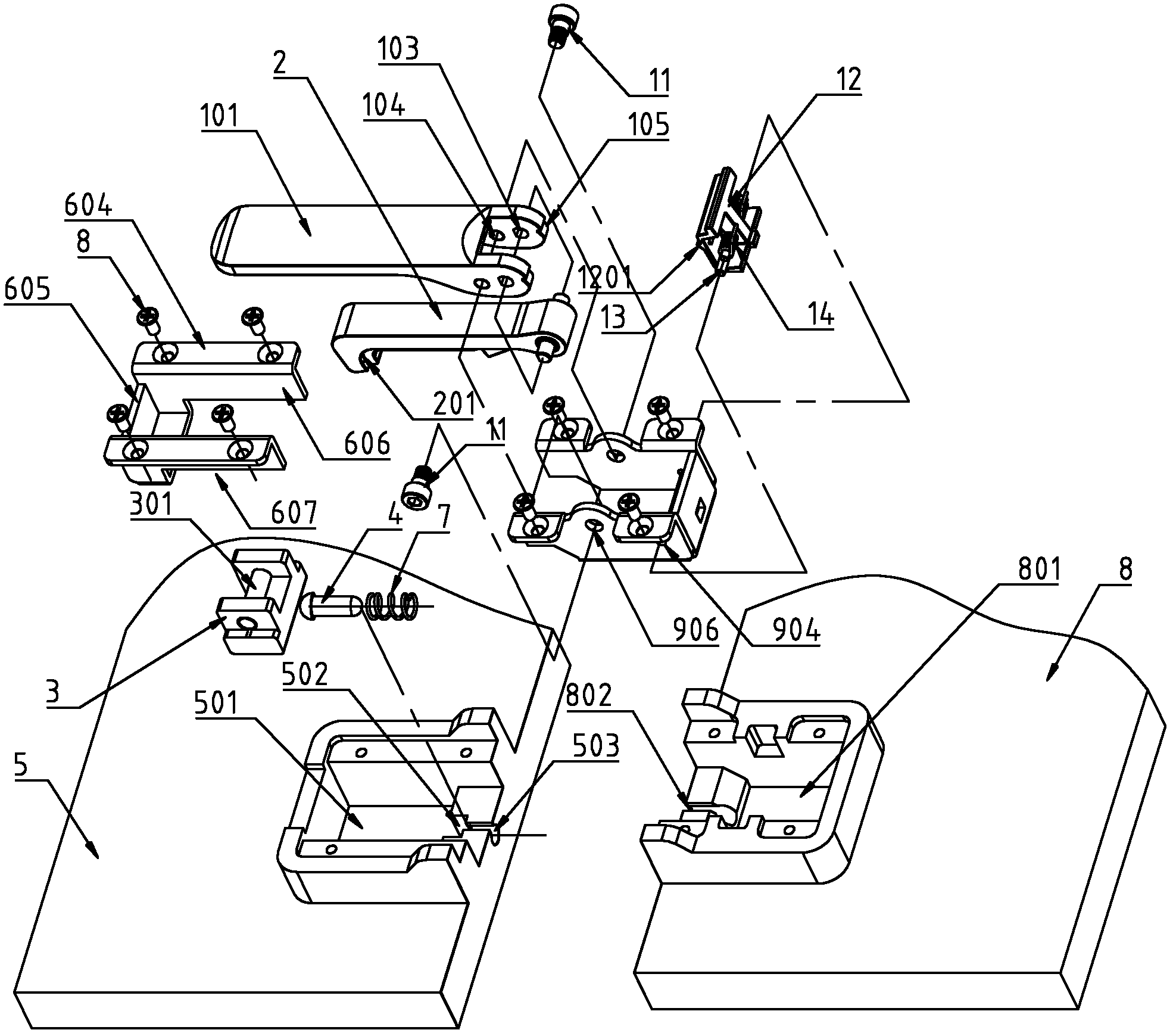
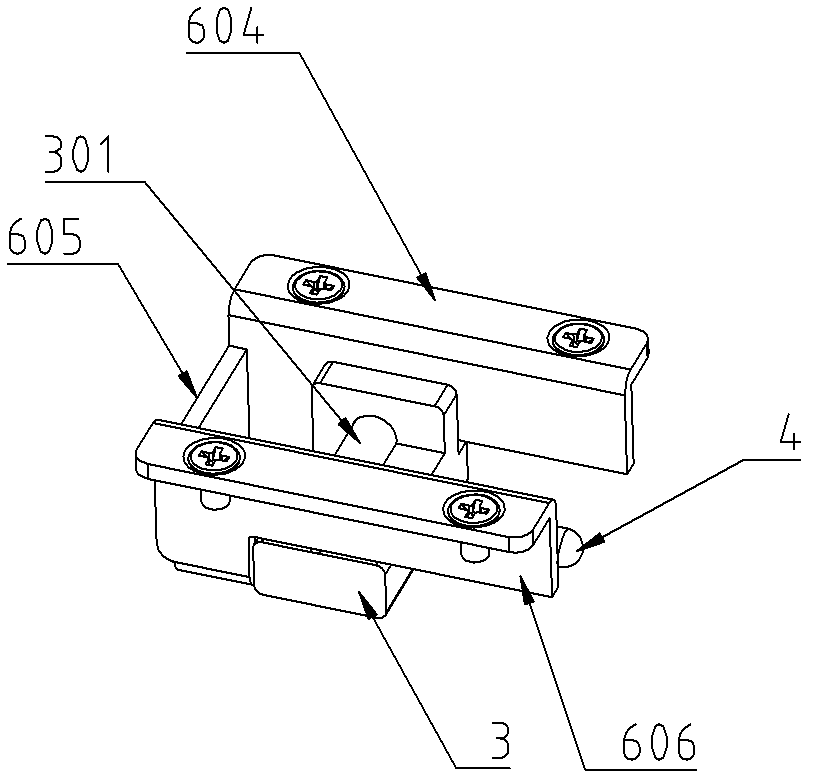
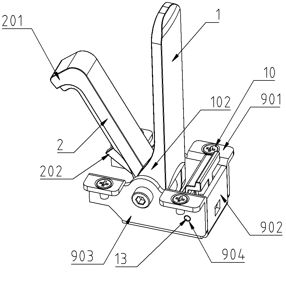
[0035] like Figure 1 to Figure 5 As shown, the locking mechanism of the LED combined screen according to Embodiment 1 of the present invention includes a first connecting portion and a second connecting portion.

[0036] The first connecting part includes a slider 3, a positioning pin 4 and a first screen.

[0037] The second connecting part includes a locking hook 2, a wrench 1 and a second screen. The lock pin is installed on the first screen plate, and the wrench 1 is hinged with the second screen plate. The rear end of the lock hook 2 is hinged with the wrench 1 , and the hinge point between the wrench 1 and the second screen is located in front of the hinge point between the lock hook 2 and the wrench 1 . The front end of the lock hook 2 has a hook head 201 .

[0038] The first screen plate includes a first plate body 5 and a groove-shaped first installation seat 6 , and the first plate body 5 has a sliding groove 501 , a spring seat 502 and a shaft hole 503 . The fi...


PUM


Abstract

The invention discloses an LED (Light Emitting Diode) combined screen latching mechanism, an LED unit screen and an LED combined screen. The LED combined screen latching mechanism comprises a first connecting part and a second connecting part, wherein the first connecting part comprises a slide block, a locating pin, a first screen board and a locating pin offsetting spring; the first screen board comprises a shaft hole of the locating pin and a longitudinal slideway of the slide block, and the locating pin is inserted to the shaft hole of the locating pin from the front to the back; the second connecting part comprises a latch hook, a wrench and a second screen board, the wrench is hinged with the second screen board, and the rear end of the latch hook is hinged with the wrench; and when the latching mechanism is latched, a hook head at the front end of the latch hook is lapped and hung on the slide block, the slide block slides along the slideway, and the rear end of the locating pin is inserted to a locating pin hole of the second screen board, so that the first screen board and the second screen board are connected together. When being used for splicing the unit screen, the LED combined screen latching mechanism is free of using an auxiliary mounting tool or high professional staff, time-saving and labor-saving purposes are achieved in the assembling process, the splicing precision is high, and the LED combined screen latching mechanism is suitable for splicing a display screen with high resolution.

Description

[technical field] [0001] The invention relates to an LED electronic display screen, in particular to a locking mechanism for an LED combined screen, an LED unit screen and an LED combined screen. [Background technique] [0002] Due to its excellent display effect and applicability, LED electronic display screens have been widely used in stages, commercial performances, advertisements, exhibitions and other industries. LED electronic display screens are generally composed of smaller unit screens. When the demand for display area is large, dozens or even hundreds of unit screens may be assembled and used together, which requires a lot of manpower and material resources of the display provider to install and disassemble. . [0003] With the growing maturity of the display screen rental market, higher requirements are put forward for the convenience and safety of display screen assembly and disassembly. The traditional LED display generally uses parts such as pull locks or con...

Claims


Application Information

Patent Timeline
IPC IPC(8): G09F9/33H05K5/02
CPCG09F9/3026
Inventor 卢伟
Owner GTEK GRP LTD
Learn More