Forming method for light bar circuit board

A molding method and circuit board technology, applied in printed circuits, printed circuit manufacturing, electrical components, etc., can solve the problems of excessive V-cut, affecting product quality, abnormal intermediate board width, etc., to ensure product quality and less difficult to operate. , The effect of improving the yield of finished boards

Active Publication Date: 2012-08-15
南通胜宏科技有限公司
View PDF1 Cites 16 Cited by
  • Summary
  • Abstract
  • Description
  • Claims
  • Application Information

AI Technical Summary

Problems solved by technology

This light bar circuit board molding method has the following disadvantages: 1. Because the aspect ratio of the light bar circuit board is more than 70:1, and the thickness of the board is relatively thin, its strength is very poor, so in step 3, the PCS board 2a is easily Extruded by the milling force of the milling cutter 3b, it is bent and deformed, and arches appear in the middle, resulting in abnormal width of the middle plate, resulting in unqualified dimensions, and ultimately affecting produc...

Method used


Image

  • Forming method for light bar circuit board
  • Forming method for light bar circuit board
  • Forming method for light bar circuit board

Examples


Embodiment Construction

[0025] In order to facilitate the understanding of those skilled in the art, the present invention will be further described in detail below with reference to the drawings and embodiments.

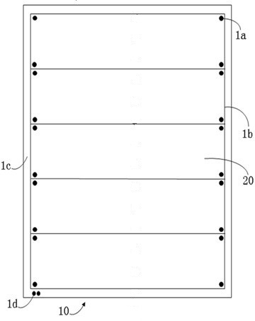
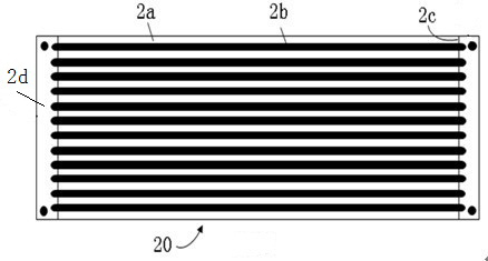
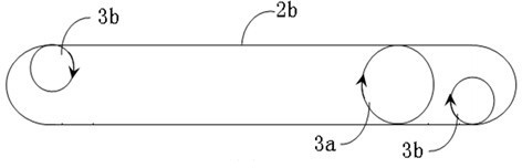
[0026] Such as Figure 4 , 5 , 6, this embodiment discloses a Light bar circuit board molding method, including the following steps:

[0027] Step one, design molding line 4b on the PNL board 40 to be formed, design five set boards 50 within the molding line 4b, and be provided with positioning holes 4a and outside the PNL board molding line at the four corners of each set board The frame bar at the bottom of the forming outer frame 4c is provided with two direction holes 4d, plant the positioning PIN according to the position of the positioning holes on the molding machine, and put the PNL board on the positioning PIN according to the direction indicated by the direction hole 4d;

[0028] Step 2: Use a forming machine to drill thirteen fixing holes 4e on the top frame bar of the forming...


PUM


Abstract

The invention relates to a forming method for a light bar circuit board, which comprises the steps of designing a forming line on a PNL (pulsed neutron log) board, designing a plurality of set boards in the forming line, arranging positioning holes at corners at four edges of each set board and arranging a plurality of direction holes in a bottom frame strip of a forming outer frame outside the PNL forming line, inserting and positioning PINs on a forming machine according to the positions of the positioning holes, and placing the PNL board on the positioning PINs in a sheathing way according to an indication direction of the direction holes, drilling a plurality of fixing holes in a top frame strip of the forming outer frame at equal intervals by using the forming machine, inserting and positioning PINs, except the top frame strip of the forming outer frame, removing the bottom frame strip, a left frame strip and a right frame strip of the forming outer frame, V-cutting V-shaped pits in the PNL board by using a V-cut machine, sheathing the V-cut PNL board on the PINs of the forming machine, striking a plurality of set boards on the PNL board within the forming outer frame from the bottom frame strip to the top frame strip of the PLN board forming outer frame according to requirements, and forming a plurality of PCS (personal communication system) boards on each set board, wherein the PCS boards are separated by forming slots, and a breaking frame formed at an area between each V-shaped pit and the forming line is connected with the PCS boards.

Description

technical field [0001] The invention relates to the technical field of photoelectric circuit board manufacturing methods, in particular to a method for forming a Light bar circuit board. Background technique [0002] Light bar circuit board is a kind of photoelectric circuit board. Light bar refers to light bar. Light bar circuit board is a light bar circuit board. Its main purpose is to provide backlight for light-emitting panels. Light bar circuit board has the characteristics of thin thickness and large aspect ratio, usually the thickness of the board is less than 0.7mm, and the aspect ratio is above 70:1. Therefore, the light-emitting panel made of this type of circuit board has thin thickness and light weight. The advantages. However, due to the thin thickness and large aspect ratio of the light bar circuit board, the forming of the light bar circuit board is more complicated than that of ordinary circuit boards. The molding method of existing Light bar circuit board ...

Claims


Application Information

Patent Timeline
IPC IPC(8): H05K3/00
Inventor 龚俊刘师锋
Owner 南通胜宏科技有限公司
Why Eureka
Try Eureka