Impact tool

一种冲击工具、工具的技术,应用在电子脉冲驱动器,新型撞击机构领域,能够解决冲击驱动器反作用增加、正转时间长、工人加重不适等问题,达到抑制峰值电流、构成控制单元简化、控制单元简化的效果

Active Publication Date: 2012-08-15
KOKI HLDG CO LTD
View PDF7 Cites 27 Cited by
  • Summary
  • Abstract
  • Description
  • Claims
  • Application Information

AI Technical Summary

Problems solved by technology

However, in this newly developed electronic pulse driver, if the forward rotation time is long during high-load work, the reaction of the impact driver is also increased, and the worker feels aggravated discomfort

Method used


Image

  • Impact tool
  • Impact tool
  • Impact tool

Examples


Embodiment Construction

[0185] Embodiments will be described below with reference to the drawings. In the following descriptions, the up-down, front-back, and left-right directions are the same as figure 1 and 2 Corresponds to the directions shown in .

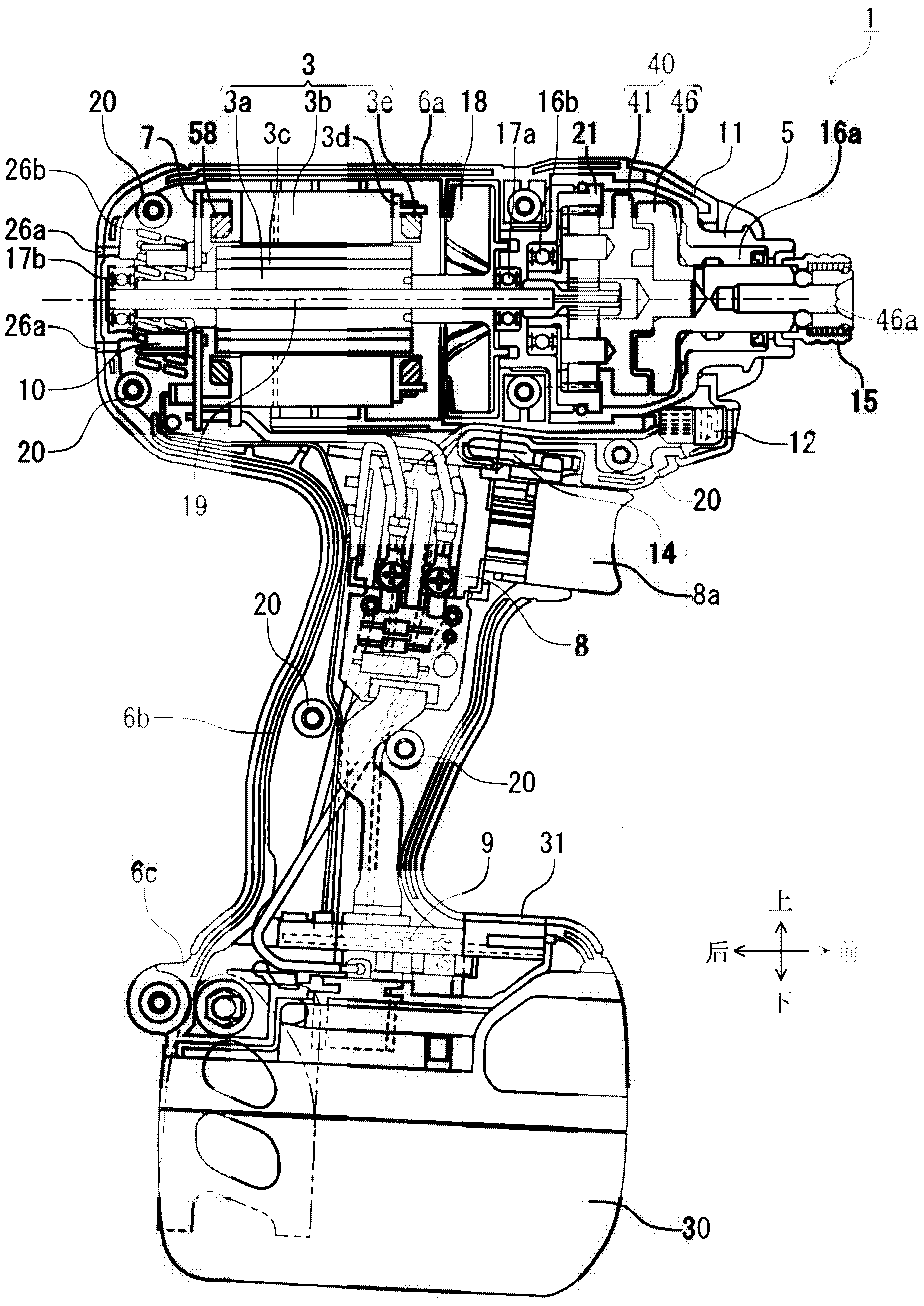
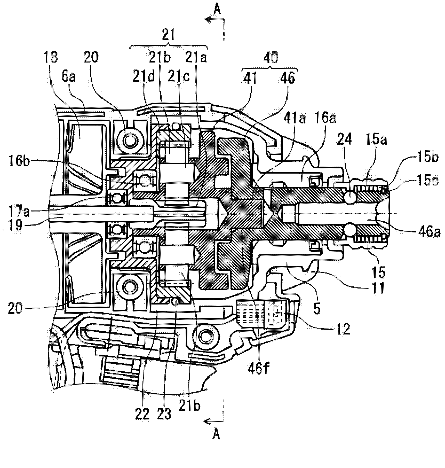
[0186] figure 1 An impact tool 1 according to one embodiment is illustrated. The impact tool 1 drives the impact mechanism 40 with the rechargeable battery pack 30 as a power source and the electric motor 3 as a driving source, and provides rotation and impact to an anvil 46 as an output shaft to transmit continuous torque or intermittent impact power to the tip A tool (not shown), such as a drill bit, is driven to perform operations such as screw tightening or bolt tightening.

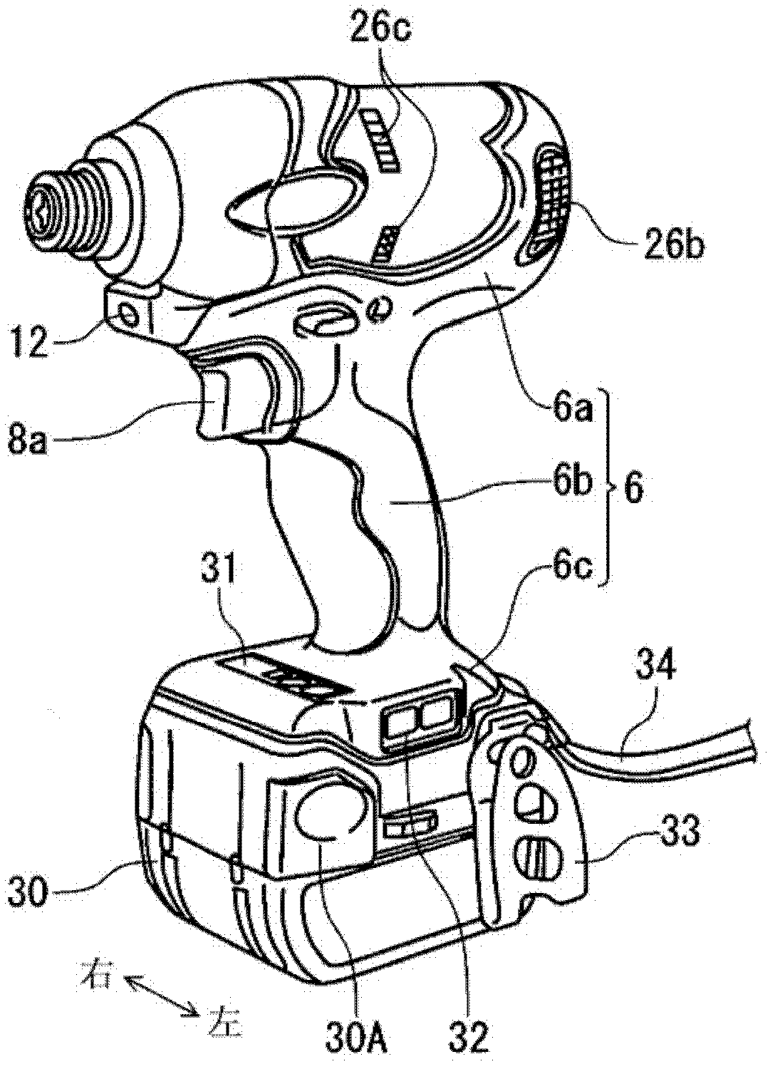
[0187] The motor 3 is a brushless DC motor, and is accommodated in a tubular trunk portion 6a of a housing 6 having a substantially T-shape when viewed from the side. The housing 6 is detachable into two substantially symmetrical right and left parts, and the right and ...


PUM


Abstract

According to an aspect of the present invention, there is provided an impact tool (1) (including: a motor (3)drivable in an intermittent driving mode; a hammer (41) connected to the motor; an anvil (16) to be struck by the hammer (41) to thereby rotate / strike a tip tool; and a control unit that controls a rotation of the motor (3)by switching a driving pulse supplied to the motor (3) in accordance with a load applied onto the tip tool.

Description

technical field [0001] An aspect of the present invention relates to an impact tool driven by an electric motor and realizes a new type of impact mechanism. [0002] Another aspect of the present invention relates to a power tool, in particular to an electronic pulse driver outputting rotational driving force. [0003] Yet another aspect of the present invention relates to a power tool, in particular to an electronic pulse driver outputting rotational driving force. [0004] Yet another aspect of the present invention relates to a power tool, in particular to an electronic pulse driver outputting rotational driving force. [0005] Yet another aspect of the present invention relates to a power tool, in particular to an electronic pulse driver outputting rotational driving force. [0006] Yet another aspect of the present invention relates to a power tool, in particular to an electronic pulse driver outputting rotational driving force. [0007] Yet another aspect of the prese...

Claims


Application Information

Patent Timeline
Patent Type & Authority Applications(China)
IPC IPC(8): B25B21/02B25B23/147
CPCB25B21/02B25B21/026B25B23/1475B25B23/147
Inventor 谷本英之高野信宏西河智雅岩田和隆益子弘识山口勇人中川淳司大森和博中村瑞穗内田洋树中野沙路磨伊藤穣
Owner KOKI HLDG CO LTD
Why Eureka
Try Eureka