Catalytic reactor including a catalytic cellular structure and at least one structural element

A technology of catalytic reactors and structural components, applied in the direction of gas-to-gas reactions under catalytically active bodies, chemical instruments and methods, chemical/physical/physicochemical processes, etc., can solve the problems of lack of conductive heat transfer, etc.

Inactive Publication Date: 2012-08-15
LAIR LIQUIDE SA POUR LETUDE & LEXPLOITATION DES PROCEDES GEORGES CLAUDE
View PDF0 Cites 1 Cited by
  • Summary
  • Abstract
  • Description
  • Claims
  • Application Information

AI Technical Summary

Problems solved by technology

[0021] - Lack of conductive heat transfer between th

Method used


Image

  • Catalytic reactor including a catalytic cellular structure and at least one structural element
  • Catalytic reactor including a catalytic cellular structure and at least one structural element
  • Catalytic reactor including a catalytic cellular structure and at least one structural element

Examples


Embodiment Construction

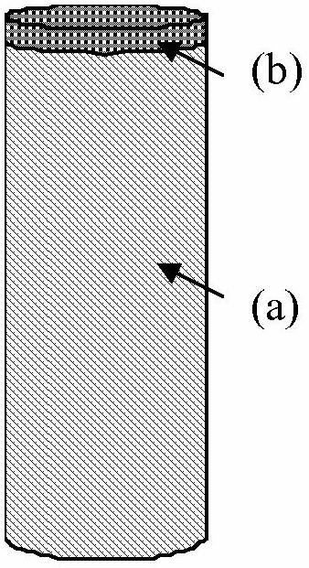
[0044] figure 1 show:

[0045] - a / some ceramic and / or metallic porous structures (a) having a controlled catalytic microstructure, and

[0046] - Static mixers (b), which are in particular metallic.

[0047]In this reactor, the catalytic bed is constructed entirely of ceramic foam in order to benefit from the concentration of catalytic activity and optimal heat transfer along the entire tube. A static mixer at the inlet prevents possible preferential flow at the walls. The static mixer is in contact with the inner wall of the reactor. Foams can also have metallic properties.

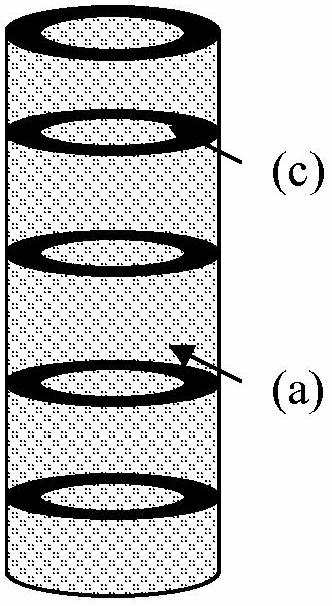
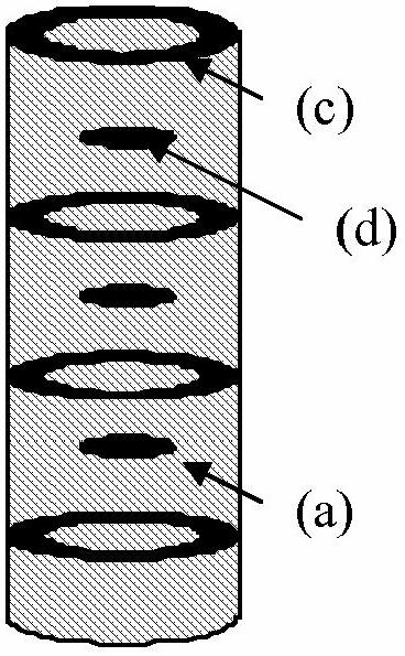
[0048] figure 2 show:

[0049] - ceramic and / or metallic porous structures (a) with a controlled catalytic microstructure (these structures are for example stacked blocks of catalytic ceramic foam), and

[0050] - preferably metallic or ceramic non-catalytic structural elements in the form of rings (c) between porous structures. For structural elements of a ceramic nature in the context, non-o...


PUM


Abstract

The invention relates to a catalytic reactor including at least two catalytic cellular architectures and at least one structural element, inserted between the two catalytic cellular architectures, in which the entire outer perimeter is in contact with the inner wall of the reactor, the cellular architecture and the structural element being arranged coaxially.

Description

technical field [0001] The subject of the invention is a catalytic reactor comprising a porous catalytic structure, in particular a catalytic ceramic or metal foam, and at least one structural element reducing the preferential flow of gases along the reactor wall and promoting heat transfer. Background technique [0002] Foams made of ceramics or even metal alloys are known to be used as catalyst supports in chemical reactions, more particularly in heterogeneously catalyzed reactions. These foams are particularly beneficial for highly exothermic or endothermic reactions (e.g., exothermic Fischer-Tropsch reactions, water-gas shift reactions, partial oxidation reactions, methanation reactions, etc.), and / or catalytic reactors requiring high space velocities (natural gas , steam reforming of naphtha, LPG, etc.). [0003] The most common method used to form ceramic foams with open macroporosity involves infiltrating a polymeric foam (usually polyurethane or polyester foam) with...

Claims


Application Information

Patent Timeline
IPC IPC(8): C01B3/48
CPCB01J12/007B01J15/005B01J19/2485B01J19/2495B01J2208/00849C01B3/16C01B3/40C01B2203/0233C01B2203/0283C01B2203/1005
Inventor P·戴-嘉罗D·加里A·屈尼M·科尼拉克
Owner LAIR LIQUIDE SA POUR LETUDE & LEXPLOITATION DES PROCEDES GEORGES CLAUDE
Why Eureka
Try Eureka