Eureka AIR delivers breakthrough ideas for toughest innovation challenges, trusted by R&D personnel around the world.

Cutting wire straightener

A technology for cutting steel wires and straighteners, applied in the field of straighteners, can solve the problems of disordered lines, knots, small cutting steel wires, etc., and achieves the effect of ensuring continuity, improving qualification rate, and increasing ring diameter.

Inactive Publication Date: 2014-10-08
ZHANGJIAGANG CITY KECHEN INSTR
View PDF7 Cites 0 Cited by
  • Summary
  • Abstract
  • Description
  • Claims
  • Application Information

AI Technical Summary

Problems solved by technology

[0003] In the process of drawing the source wire into the cutting steel wire, due to the different degrees of deviation between the direction of the cutting steel wire and the center of the mold, this deviation cannot be solved in the prior art, and the cutting steel wire is partially extruded and rubbed when passing through the die opening. , causing the cutting wire to spiral and bend regularly in the natural state after it comes out of the die, and the greater the above-mentioned deviation, the smaller the bending diameter of the cutting wire and the greater the stress
This kind of small-diameter cutting steel wire is easy to produce messy wires, knots, breakage, etc. when cutting workpieces.
If there are joints in the source wire, unsatisfactory heat treatment, or uneven copper plating, etc., it cannot be detected in the existing drawing process, which is especially prominent when the workpiece is subsequently cut, which will bring great harm to the user. big loss

Method used


Image

  • Cutting wire straightener
  • Cutting wire straightener
  • Cutting wire straightener

Examples


Embodiment Construction

[0018] Specific embodiments of the present invention will be described in detail below in conjunction with the accompanying drawings.

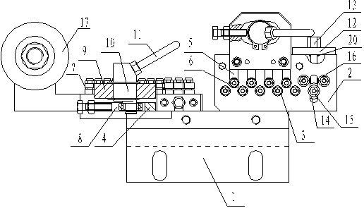
[0019] Such as figure 1 As shown, the first embodiment of the cutting wire straightener according to the present invention includes a base plate 1 on which there is a horizontally placed straightening device and a vertically placed straightening device. The straightening device includes a backing plate 2, on which a row of fixed bearings 3 is fixed by screws, a slide plate 4 is arranged on one side of the backing plate 2, and one end of the slide plate 4 is inserted into the backing plate 2, and the pad on one side of the slide plate 4 The plate 2 is provided with several waist-shaped holes 5, and there are several sliding bearings 6 on one side of the backing plate 2, and the sliding bearings 6 are respectively fixed on the slide plate 4 at the waist-shaped holes 5 by bolts, and the fixed bearings 3 and the sliding bearings 6 The surface of ...


PUM


Abstract

The invention discloses a straightener for a cut steel wire, which can greatly increase the natural circular diameter of the cut steel wire and can detect an unqualified source wire. The straightener comprises a base plate, a horizontally placed straightening device and a vertically placed straightening device, wherein the straightening device comprises a cushion plate; slide blocks are arranged in the cushion plate; bearings are fixedly arranged on the slide blocks; the adjacent bearings are alternately arranged and formed into upper and lower two rows of bearings; an S-shaped steel wire channel is formed between the upper and lower two rows of bearings; a fixing plate and an adjusting plate are arranged on one side of the cushion plate in turn; bolts pass through the adjusting plate and the fixing plate and are respectively in threaded connection with one ends of the slide blocks; two limiting sleeves are respectively and fixedly arranged on each bolt corresponding to the lower row of bearings and are respectively located on two sides of the fixing plate; a limiting sleeve is fixedly arranged on each bolt corresponding to the upper row of bearings; the limiting sleeves and bolt heads are respectively located on two sides of the adjusting plate; and the straightening device further comprises an adjusting device for pushing the adjusting plate to move up and down.

Description

[0001] (The name of the original invention is a cutting wire straightener, the application date is December 15, 2010, and the application number is 201010589625.8) technical field [0002] The invention relates to a straightener for fine steel wires, in particular to a straightener for cutting steel wires. Background technique [0003] In the process of drawing the source wire into the cutting steel wire, due to the different degrees of deviation between the direction of the cutting steel wire and the center of the mold, this deviation cannot be solved in the prior art, and the cutting steel wire is partially extruded and rubbed when passing through the die opening. , causing the cutting steel wire to spiral and bend regularly in a natural state after it comes out of the die, and the greater the above-mentioned deviation, the smaller the bending diameter of the cutting steel wire and the greater the stress. This small-diameter cutting steel wire is easy to produce messy wire...

Claims


Application Information

Patent Timeline
Patent Type & Authority Patents(China)
IPC IPC(8): B21F1/02
Inventor 陈建明
Owner ZHANGJIAGANG CITY KECHEN INSTR
Why Eureka
Eureka Blog
Learn More