Unlock instant, AI-driven research and patent intelligence for your innovation.

Airplane high lift device with single slotted flaps

A technology of increasing lift device and flaps, which is applied in the field of aircraft design, can solve the problems of small flap retreat, small cruising additional resistance, large flap movement mechanism, etc., and achieves reduced fuel consumption, wide application range, high lift-drag The effect of improving

Inactive Publication Date: 2012-08-22
XIAN AIRCRAFT DESIGN INST OF AVIATION IND OF CHINA
View PDF6 Cites 4 Cited by
  • Summary
  • Abstract
  • Description
  • Claims
  • Application Information

AI Technical Summary

Problems solved by technology

[0002] There are two types of aircraft lift devices with traditional single-slot flaps: the first single-slot flap 2-lift device (such as figure 1 As shown), the first hinge 6 is slightly lower than the lower surface of the airfoil, the flap motion mechanism is small, and the cruise additional resistance generated is small, which has little influence on the cruise lift-drag ratio of the aircraft, but the first single-slot flap 2 The disadvantage of the high-lift device is that the amount of flap retreat is small. In order to obtain a large enough passage, the lower part of the flap compartment 12 must be open, which leads to the first type of single-slot flap 2 high-lift device is only suitable for low-speed aircraft. Narrower range; the second type of flap 2 high-lift device (such as figure 2 As shown), the first hinge 6 is located far below the lower surface of the airfoil, which can produce sufficient retreat, but the flap motion mechanism is relatively large, and the additional cruise resistance generated is relatively large, which reduces the cruise lift-to-drag ratio of the aircraft

Method used


Image

  • Airplane high lift device with single slotted flaps
  • Airplane high lift device with single slotted flaps
  • Airplane high lift device with single slotted flaps

Examples


Embodiment Construction

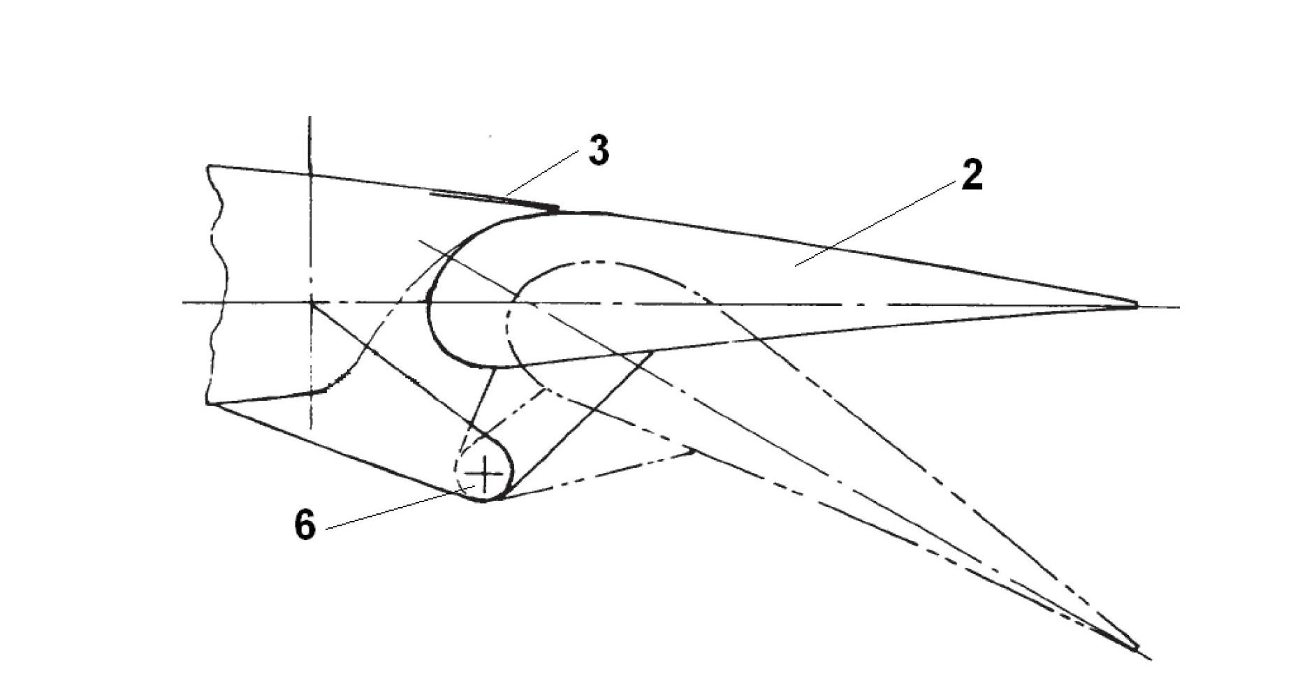
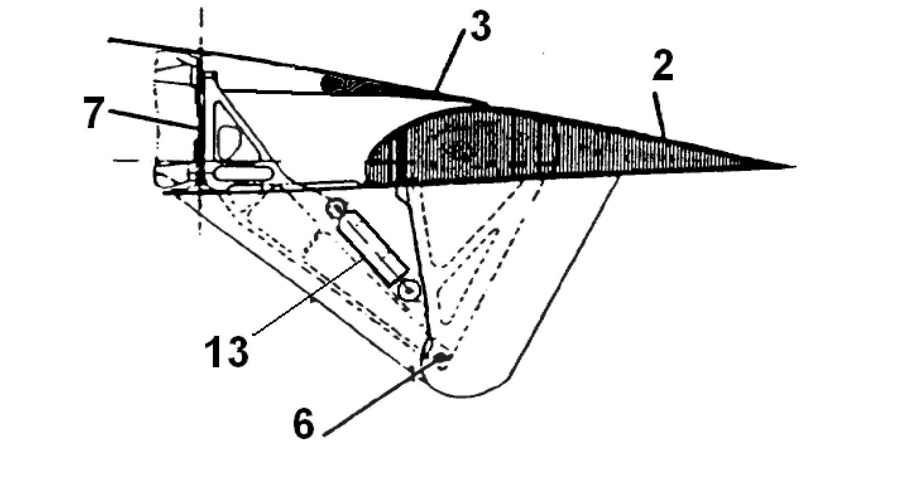
[0013] The present invention will be described in detail below in conjunction with the accompanying drawings. Such as figure 2 , the lifting device includes flap 2, main wing rear beam fixing rod 14, flap front beam fixing rod 16, flap rear beam fixing rod 17, linkage rod 11, lower baffle plate 4, sealing rubber 5, actuator 13, main wing rear beam One end of the fixed rod 14 is fixed on the lower part of the rear beam 7 on the main wing 1, the width of the main wing rear beam fixed rod 14 is the same as the width of the lower edge of the rear beam 7, and the other end of the main wing rear beam fixed rod 14 is connected to the flap front beam through the first hinge 6 One end of the fixed rod 16 is hinged, and the width of the main wing rear beam fixed rod 14 gradually changes to the same diameter as the first hinge 6; the other end of the flap front beam fixed rod 16 is fixed on the lower part of the front beam 9 in the flap 2, and the fixed rod The width of 16 is the same ...


PUM


Abstract

The invention belongs to the field of airplane design and relates to an airplane high lift device with single slotted flaps for increasing the lift force of an airplane to take off and land. The high lift device comprises flaps, a main wing rear spar fixed link, a flap front spar fixed link, a flap rear spar fixed link, a linkage rod, a lower baffle plate, a stripper rubber and an actuator cylinder. The airplane high lift device with single slotted flaps, provided by the invention, can be used for improving the high lift capacity of the airplane and increasing the maximum lift coefficient of the airplane by 8%-15% and the loading capacity by 8%-15%. A movement mechanism provided by the invention has smaller windward area, which can decrease the cruising resistance of the airplane by 0.5%-1.5% and the fuel oil consumption by 0.5%-1.5%. According to the invention, the lower baffle plate in a flap cabin can properly decrease the noise generated by the airplane by 2-5dB during the taking off and landing of the airplane, and thus the airplane is more environmentally-friendly. The lower baffle plate in the flap cabin can be used for increasing the lift-drag ratio of the airplane by 3%-6% during the taking off of the airplane, so that the airplane is safer with greater rate of climb.

Description

technical field [0001] The invention belongs to the field of aircraft design, and relates to an aircraft lift-increasing device with a single-slit flap used for increasing the lift force of the aircraft when the aircraft takes off and lands. Background technique [0002] There are two types of aircraft lift devices with traditional single-slot flaps: the first single-slot flap 2-lift device (such as figure 1 As shown), the first hinge 6 is slightly lower than the lower surface of the airfoil, the flap motion mechanism is small, and the cruise additional resistance generated is small, which has little influence on the cruise lift-drag ratio of the aircraft, but the first single-slot flap 2 The disadvantage of the high-lift device is that the amount of flap retreat is small. In order to obtain a large enough passage, the lower part of the flap compartment 12 must be open, which leads to the first type of single-slot flap 2 high-lift device is only suitable for low-speed aircra...

Claims


Application Information

Patent Timeline
IPC IPC(8): B64C9/24
Inventor 王银虎段卓毅张宏周若君吉桂兴
Owner XIAN AIRCRAFT DESIGN INST OF AVIATION IND OF CHINA
Features
  • R&D
  • Intellectual Property
  • Life Sciences
  • Materials
  • Tech Scout
  • Unparalleled Data Quality
  • Higher Quality Content
  • 60% Fewer Hallucinations
Learn More