Light-mixing-type polycrystalline packaging structure

A packaging structure and light mixing technology, applied in the direction of light source, lighting device, light source fixing, etc., can solve the problem of insufficient color rendering, and achieve the effect of improving color rendering

Inactive Publication Date: 2012-08-22
PARAGON SEMICON LIGHTING TECH
View PDF8 Cites 11 Cited by
  • Summary
  • Abstract
  • Description
  • Claims
  • Application Information

AI Technical Summary

Problems solved by technology

However, the traditional light-emitting structures made of light-emitting diodes have insufficient color rendering.

Method used


Image

  • Light-mixing-type polycrystalline packaging structure
  • Light-mixing-type polycrystalline packaging structure
  • Light-mixing-type polycrystalline packaging structure

Examples


Embodiment 1

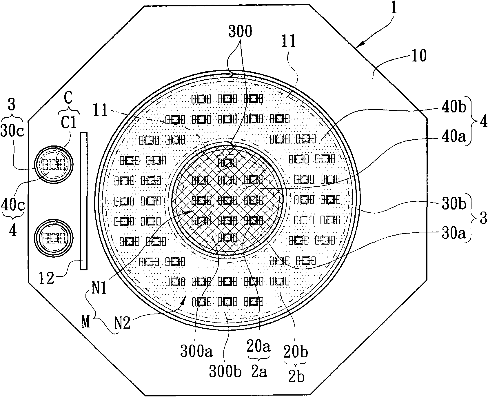
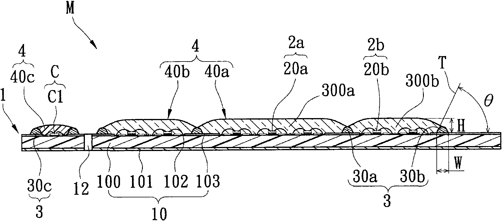
[0078] see Figure 1A and Figure 1B As shown, Embodiment 1 of the present invention provides a light-mixing polycrystalline packaging structure M, which includes: a substrate unit 1 , a light emitting unit, a frame unit 3 and a packaging unit 4 .

[0079] The substrate unit 1 has at least one substrate body 10 and at least two crystal mounting regions 11 disposed on the upper surface of the substrate body 10 . In addition, the substrate body 10 has a circuit substrate 100, a heat dissipation layer 101 disposed on the bottom of the circuit substrate 100, a plurality of conductive pads 102 disposed on the upper surface of the circuit substrate 100, and a plurality of conductive pads 102 disposed on the upper surface of the circuit substrate 100 for exposing The insulating layer 103 of the plurality of conductive pads 102 . Therefore, the heat dissipation layer 101 can be used to increase the heat dissipation performance of the circuit substrate 100 , and the plurality of insul...

Embodiment 2

[0092] see figure 2 As shown, Embodiment 2 of the present invention provides a light-mixing polycrystalline packaging structure M. Depend on figure 2 Comparison with Fig. 1 shows that the biggest difference between Embodiment 2 and Embodiment 1 of the present invention is that in Embodiment 2, the positions of the first light-emitting module 2a and the second light-emitting module 2b are reversed, so that the first light-emitting module 2a placed in the outer circle, and the second light-emitting module 2b is placed in the inner circle. In other words, the first surrounding frame glue 30a surrounds the second light emitting module 2b, the second surrounding frame glue 30b surrounds the first light emitting module 2a and the first surrounding frame glue 30a, and the first light emitting module 2a is arranged on the first surrounding frame Between the frame glue 30a and the second surrounding frame glue 30b. The fluorescent colloid 40b is confined in the first colloid limit...

Embodiment 3

[0095] see image 3 As shown, Embodiment 3 of the present invention provides a light-mixing polycrystalline packaging structure M, which includes: a substrate unit 1 , a light emitting unit, a frame unit 3 and a packaging unit 4 . The biggest difference between Embodiment 3 of the present invention and Embodiment 1 is that in Embodiment 3, according to different design requirements, the first surrounding frame colloid 30a and the second surrounding frame colloid 30b can be transparent colloid or fluorescent colloid one of them. For example, the present invention can selectively add fluorescent powder in the first surrounding frame colloid 30a and the second surrounding frame colloid 30b according to different requirements, so that the light source can be guided to the transparent colloid 40a and the fluorescent powder. Light is emitted between the colloids 40b (shown by upward or slanting arrows in the figure), thereby reducing the dark band between the transparent colloid 40...


PUM

PropertyMeasurementUnit
Heightaaaaaaaaaa
Widthaaaaaaaaaa
Widthaaaaaaaaaa

Abstract

The invention relates to a light-mixing-type polycrystalline packaging structure, which comprises a substrate unit, a light-emitting unit, a frame unit and a packaging unit. The first light-emitting module of the light-emitting unit is provided with a plurality of red light-emitting diode crystal grains which are arranged on the substrate unit. The second light-emitting module of the light-emitting unit is provided with a plurality of blue light-emitting diode crystal grains which are arranged on the substrate unit. The first surrounding-type frame colloids of the frame unit surround the first light-emitting module. The second surrounding-type frame colloids of the frame unit surround the second light-emitting module and the first surrounding-type frame colloids. The transparent colloids and the fluorescent colloids of the packaging unit respectively cover the first light-emitting module and the second light-emitting module. Color rendering is improved through mutual light mixing of a red light source produced after the red light-emitting diode crystal grains are matched with the transparent colloids and a white light source produced after the blue light-emitting diode crystal grains are matched with the fluorescent colloids.

Description

technical field [0001] The invention relates to a light-mixing polycrystalline packaging structure, in particular to a light-mixing polycrystalline packaging structure for increasing color rendering. Background technique [0002] The invention of electric light can be said to have completely changed the way of life of all human beings. If we live without electric light, all work will stop at night or when the weather is bad; The way of construction or the way of life of human beings will be completely changed, and all human beings will not be able to progress because of this, and will continue to stay in a relatively backward age. Therefore, the lighting equipment used in the market today, such as fluorescent lamps, tungsten lamps, and even the energy-saving light bulbs that are widely accepted by the public, have been widely used in daily life. However, most of these lamps have disadvantages such as fast light decay, high power consumption, high heat generation, short life...

Claims


Application Information

Patent Timeline
IPC IPC(8): F21V19/00F21Y101/02F21Y115/10
Inventor 钟嘉珽戴世能吴朝钦
Owner PARAGON SEMICON LIGHTING TECH
Why Eureka
Try Eureka