Optical waveguide resonator with high polarization extinction ratio based on tilted waveguide grating structure

A technology of polarization extinction ratio and inclined waveguide, which is applied in the coupling direction of optical waveguide, can solve the problems of inability to obtain polarization extinction ratio and restrict the performance of RMOG, and achieve the effect of light weight, small volume and improved performance

Inactive Publication Date: 2014-10-15
ZHEJIANG UNIV
View PDF5 Cites 0 Cited by
  • Summary
  • Abstract
  • Description
  • Claims
  • Application Information

AI Technical Summary

Problems solved by technology

However, none of the above techniques can obtain sufficient polarization extinction ratio, which further restricts the performance of RMOG

Method used


Image

  • Optical waveguide resonator with high polarization extinction ratio based on tilted waveguide grating structure
  • Optical waveguide resonator with high polarization extinction ratio based on tilted waveguide grating structure

Examples


Embodiment Construction

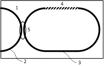
[0015] Such as figure 1 As shown, a high polarization extinction ratio optical waveguide resonator based on a tilted waveguide grating structure: an input / output optical path 2 and a resonant ring 3 are provided on the optical waveguide chip 1 body; the two ends of the input / output optical path 2 are located at The edge of the optical waveguide chip 1; the resonant ring 3 is connected to the input / output optical path 2 through the input / output coupler 5 to form a reflective optical waveguide resonator; the resonant ring 3 is etched with a slanted waveguide grating 4; the slanted waveguide grating 4 The angle between the reflective interface and the light transmission direction θ=arctan(n 2 / n 1 ), where n 1 is the refractive index of the cladding part of the optical waveguide chip 1, n 2 is the refractive index of the core layer of the optical waveguide chip 1; the etching depth of the inclined waveguide grating 4 is greater than zero and smaller than the core layer thickn...


PUM


Abstract

The invention discloses an optical waveguide resonant cavity with a high polarization extinction ratio based on an inclined waveguide grating structure. An optical waveguide chip body is provided with an input / output light channel and a resonant ring, wherein the two ends of the input / output light channel are positioned on the edge of an optical waveguide chip; the resonant ring is connected with the input / output light channel through an input / output coupler, so that an optical waveguide resonant cavity is formed; an inclined waveguide grating is etched on the resonant ring; the included angle between the reflecting interface of the inclined waveguide grating and a light ray transmitting direction is shown in the specifications, wherein n1 is the refractive index of an optical waveguide chip cladding part, and n2 is the refractive index of an optical waveguide chip sandwich layer part; and the etching depth of the inclined waveguide grating is more than zero and less than the thickness of an optical waveguide chip sandwich layer. According to the optical waveguide resonant cavity, the defect of the absence of an effective means for suppressing polarization fluctuation noise for the optical waveguide resonant cavity is overcome; and the optical waveguide resonant cavity can be applied in other fields of resonant micro-optical gyroscopes and the like, and has important scientific meaning and application value.

Description

technical field [0001] The invention relates to an optical waveguide resonant cavity, in particular to an optical waveguide resonant cavity with high polarization extinction ratio based on an inclined waveguide grating structure. Background technique [0002] The optical waveguide ring resonator is the core sensitive part of the Resonator Micro Optic Gyro (RMOG). One of the output terminals of a 2×2 optical waveguide coupler is connected to one of the input terminals to form a The most basic reflective optical waveguide resonator structure; the transmissive resonant cavity structure is composed of two 2×2 optical waveguide couplers. In the optical waveguide resonator, except for special cases, there are two intrinsic polarization states (Eigenstate of polarization, ESOP). Typically, one ESOP is orthogonal to another ESOP. Due to the influence of environmental factors, the shape of the ESOP is changing and moving independently of each other, which creates noise in the outpu...

Claims


Application Information

Patent Timeline
Patent Type & Authority Patents(China)
IPC IPC(8): G02B6/34
Inventor 马慧莲陈振金仲和
Owner ZHEJIANG UNIV
Why Eureka
Try Eureka