
LED backlight drive circuit, liquid crystal display device and drive circuit
A technology of backlight driving circuit and LED light bar is applied in the field of driving circuit, which can solve the problems such as inability to achieve, and achieve the effect of simple circuit.
- Summary
- Abstract
- Description
- Claims
- Application Information
AI Technical Summary
Problems solved by technology
Method used
Image

Examples
Embodiment Construction
[0020] The present invention will be further described below in conjunction with the accompanying drawings and preferred embodiments.
[0021] The invention discloses an LED backlight driving circuit and a liquid crystal display device based on the LED backlight driving circuit.
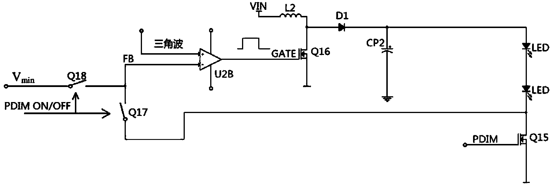
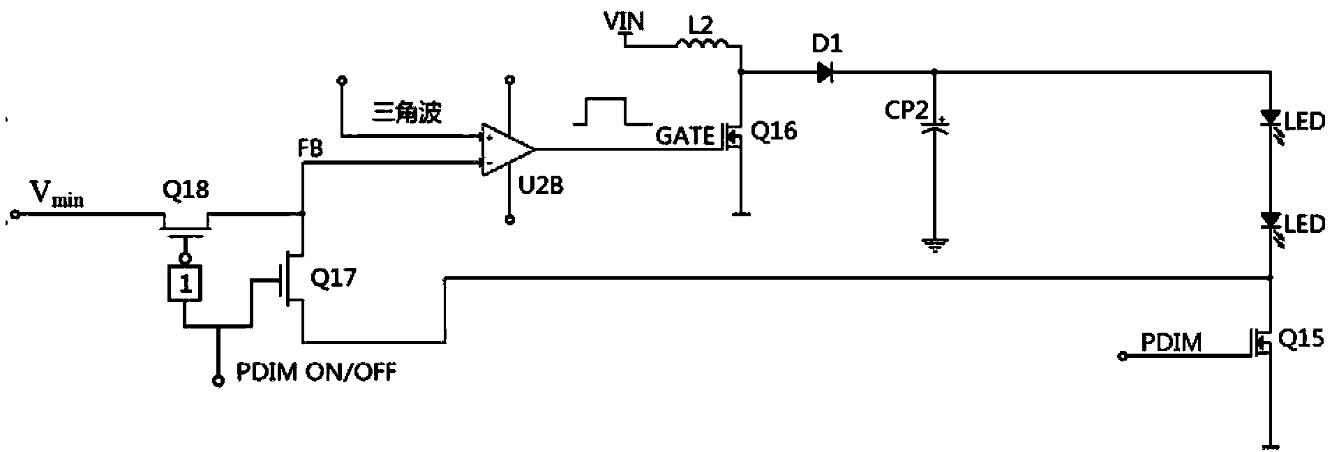
[0022] Such as figure 2 As shown, the LED backlight driving circuit includes a power module, an LED light bar coupled to the output end of the power module, a dimming module coupled to the output end of the LED light bar, a comparator, and a switch. The first input terminal SW1 of the switch is coupled to the output terminal of the LED light bar, and the second input terminal SW2 is coupled to a feedback voltage V min ; Its output terminal is coupled to the power supply module through a comparator; the switching switch is switched to the first input terminal when the dimming module is turned on; it is switched to the second input terminal when the dimming module is turned off.
[0023] The power m...
PUM
 Abstract
Description
Claims
Application Information