
Audio noise reduction method and device

An audio noise reduction and audio technology, applied in the field of audio noise reduction methods and devices, can solve the problems of increasing chip area and chip power consumption

Pending Publication Date: 2022-04-22
KTMICRO ELECTRONICS
View PDF0 Cites 0 Cited by
  • Summary
  • Abstract
  • Description
  • Claims
  • Application Information

AI Technical Summary

Problems solved by technology

Obviously, the former will increase the power consumption of the chip, and the latter will increase the chip area
In the case of chip power consumption and cost requirements, the above method will not be a good choice

Method used


Image

  • Audio noise reduction method and device
  • Audio noise reduction method and device
  • Audio noise reduction method and device

Examples


Embodiment 1

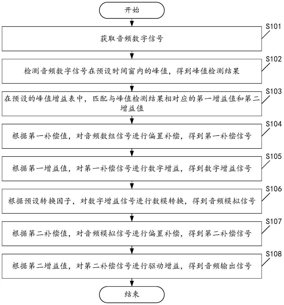
[0045] Please see figure 1 , figure 1 A schematic flowchart of an audio noise reduction method is provided for the embodiment of the present application. Wherein, the audio noise reduction method includes:

[0046] S101. Acquire an audio digital signal.

[0047] S102. Detect a peak value of the audio digital signal within a preset time window, and obtain a peak detection result.

[0048] In this embodiment, the method can perform peak detection on each packet of digital signal data.

[0049] S103. In the preset peak gain table, match the first gain value and the second gain value corresponding to the peak detection result.

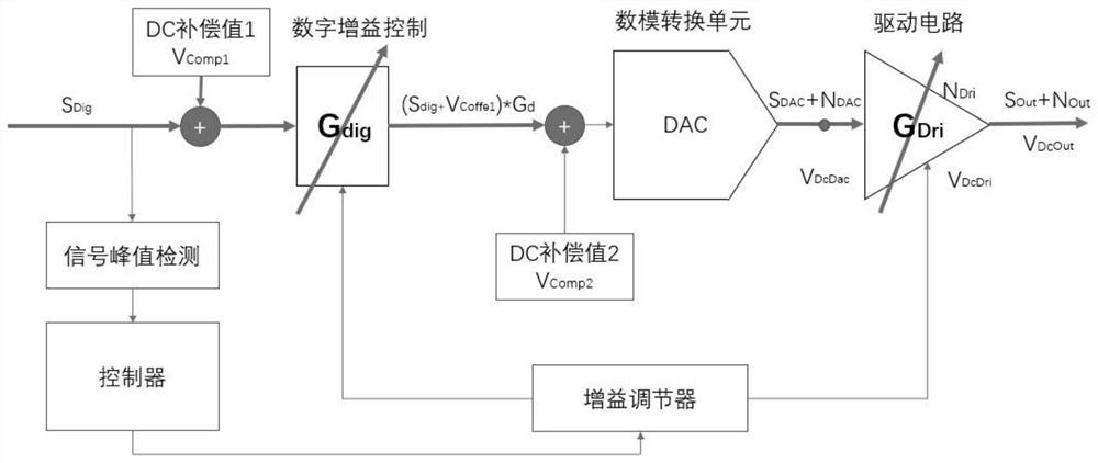
[0050] In this embodiment, the method can calculate the gain gear that should be applied at this time in the gain controller according to the peak value detected in the set time window, and configure the gain value to the gain regulator.

[0051] In this embodiment, the gain adjuster simultaneously controls the digital gain and the driving gain accord...

Embodiment 2

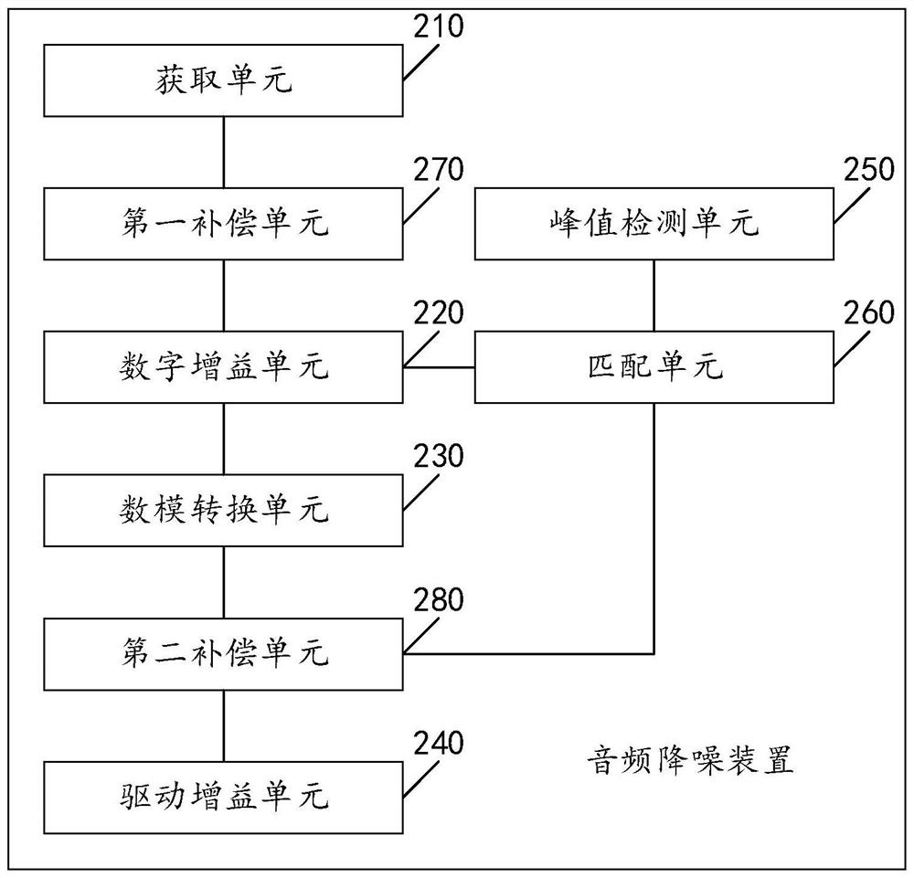
[0102] Please see figure 2 , figure 2 It is a schematic structural diagram of an audio noise reduction device provided in an embodiment of the present application. like figure 2 As shown, the audio noise reduction device includes:

[0103] An acquisition unit 210, configured to acquire an audio digital signal;

[0104] A digital gain unit 220, configured to digitally gain the audio digital signal according to the first gain value to obtain a digital gain signal;

[0105] A digital-to-analog conversion unit 230, configured to perform digital-to-analog conversion on the digital gain signal according to a preset conversion factor to obtain an audio analog signal;

[0106] The driving gain unit 240 is configured to perform driving gain on the audio analog signal according to the second gain value to obtain an audio output signal; wherein the gain product of the first gain value and the second gain value is one.

[0107]As an optional implementation manner, the first gain v...


PUM


Abstract

The invention provides an audio noise reduction method and device. The method comprises the following steps: acquiring an audio digital signal; performing offset compensation on the audio array signal according to the first compensation value to obtain a first compensation signal; performing digital gain on the first compensation signal according to the first gain value to obtain a digital gain signal; performing digital-to-analog conversion on the digital gain signal according to a preset conversion factor to obtain an audio analog signal; performing offset compensation on the audio analog signal according to the second compensation value to obtain a second compensation signal; performing driving gain on the second compensation signal according to the second gain value to obtain an audio output signal; wherein the gain product of the first gain value and the second gain value is one. Therefore, by implementing the implementation mode, the noise can be suppressed under the condition that the chip area and the chip power consumption are not obviously increased, so that the output signal-to-noise ratio of the audio is improved; meanwhile, the problem that POP sound is easily generated in an existing noise reduction structure and an existing noise reduction method can be solved.

Description

technical field [0001] The present application relates to the technical field of audio processing, and in particular, to an audio noise reduction method and device. Background technique [0002] In the field of audio processing, processing noise is a very common operation. It is well known that the main factors affecting noise are thermal noise and flicker noise of analog circuits. Among them, the common method for thermal noise suppression is to increase the drive current, and for flicker noise suppression, it is usually used to increase the size of related analog circuit devices. Obviously, the former will increase the power consumption of the chip, and the latter will increase the chip area. In the case of chip power consumption and cost requirements, the above method will not be a good choice. Contents of the invention [0003] The purpose of the embodiment of the present application is to provide an audio noise reduction method and device, which can suppress the no...

Claims


Application Information

Patent Timeline
Patent Type & Authority Applications(China)
IPC IPC(8): G10L21/0208
CPCG10L21/0208
Inventor 李锡广李振陈博文王蕊
Owner KTMICRO ELECTRONICS
Learn More