
Thin film transistor, manufacturing method and organic light emitting diode display device

A technology for thin film transistors and light emitting diodes, which is applied in the manufacture of transistors, semiconductor/solid-state devices, semiconductor devices, etc., can solve the problems such as the inability to effectively suppress the floating body effect, the increase of the area of ​​the thin film transistor, and the significant floating body effect, so as to suppress the floating body effect and increase the area, the effect of improving electrical characteristics

Active Publication Date: 2015-06-24
KUNSHAN GO VISIONOX OPTO ELECTRONICS CO LTD
View PDF6 Cites 0 Cited by
  • Summary
  • Abstract
  • Description
  • Claims
  • Application Information

AI Technical Summary

Problems solved by technology

However, this technology will increase the area of ​​thin film transistors, and the floating body effect cannot be effectively suppressed due to the existence of polysilicon (poly-Si) body resistance, and the wider the channel, the greater the body polysilicon (poly-Si) resistance, and the more significant the floating body effect

Method used


Image

  • Thin film transistor, manufacturing method and organic light emitting diode display device
  • Thin film transistor, manufacturing method and organic light emitting diode display device
  • Thin film transistor, manufacturing method and organic light emitting diode display device

Examples


Embodiment Construction

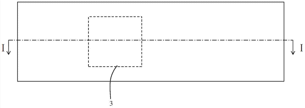
[0046] Figure 1A A plan view showing the first step of a method of manufacturing a TFT according to an exemplary embodiment of the present invention, Figure 1B for along Figure 1A A cross-sectional view taken along the line I-I. see Figure 1A with 1B A substrate 1 is provided, the substrate 1 is formed of glass or plastic, and a buffer layer 2 is formed on the substrate 1, and the buffer layer 2 is formed on the substrate 1 by chemical vapor deposition (CVD). The function of the buffer layer 2 is to prevent moisture or impurities in the substrate from diffusing into the semiconductor layer, or to control heat transfer efficiency during crystallization to make crystallization of the semiconductor layer easier, which will be formed in the following process. The buffer layer 2 can be a single layer, or can be composed of multi-layer films.

[0047] Subsequently, a first amorphous silicon layer is formed on the buffer layer 2 . It can be formed by chemical vapor deposition ...


PUM


Abstract

The invention provides a thin film transistor, a manufacturing method and an organic light emitting diode display device. The thin film transistor comprises a first semiconductor layer, a second semiconductor layer, a gate insulation layer and a gate metal layer, the second semiconductor layer is deposited on the first semiconductor layer, the gate insulation layer is located above the second semiconductor layer, and the gate metal layer is located above the gate insulation layer. A source region, a drain region and a channel region between the source region and the drain region are formed on the second semiconductor layer, the first semiconductor layer is located below the source region or the drain region and extends out of the coverage of the second semiconductor layer to form a body contact region, and the body contact region can be electrically connected with the source region or the gate metal layer. Through the arrangement, the floating body effect can be effectively restrained.

Description

technical field [0001] The invention relates to the field of display technology, in particular to a thin film transistor, a manufacturing method and an organic light emitting diode display device thereof. Background technique [0002] Organic light-emitting diode (OLED) display device is an active light-emitting device. Compared with the current mainstream flat-panel display technology thin-film transistor liquid crystal display (TFT-LCD), OLED has the advantages of high contrast, wide viewing angle, low power consumption, and thinner volume. , is expected to become the next-generation flat panel display technology after LCD, and is one of the most concerned technologies in flat panel display technology, especially suitable for large-sized active matrix organic light emitting diode (Active Matrix OLED, AMOLED) display devices. Polycrystalline silicon (poly-Si) with higher mobility is widely used as thin film transistors due to the large demand for driving current in OLEDs an...

Claims


Application Information

Patent Timeline
IPC IPC(8): H01L29/786H01L27/32H01L21/336
CPCH01L29/6675H01L29/78615H01L29/78672H10K59/12H10K59/10
Inventor 杜哲陆海峰
Owner KUNSHAN GO VISIONOX OPTO ELECTRONICS CO LTD
Learn More