Radio frequency transmitting circuit

a technology of transmitting circuit and radio frequency, which is applied in the direction of transmission monitoring, single-ended push-pull amplifier, modulation, etc., can solve the problems of inability to avoid outputting transmission power, disadvantageously unsuited isolator for miniaturization, and conventional transmitting circuit not suited to the reduction of consumption power

Inactive Publication Date: 2001-12-11
NEC CORP
View PDF9 Cites 78 Cited by
  • Summary
  • Abstract
  • Description
  • Claims
  • Application Information

AI Technical Summary

Benefits of technology

If the second switch is switched in a time division manner to select the direct current voltage corresponding to the reflected wave, the gate voltage control means applies a gate voltage suited for the load impedance to the final stage amplifier in accordance with the direct current voltage corresponding to the reflected wave. Thus, it is possible to miniaturize a mobile communication equipment, reduce consumption power and make the final stage amplifier exhibit excellent electrical characteristics.
As stated so far, according to this invention, the reflected wave generated by the mismatching between the output impedance of the final stage amplifier and the load impedance connected to the output of the final stage amplifier is detected, and the gate voltage suited for the load impedance is applied to the gate of the final stage amplifier by the gate voltage control means. As a result, it is possible to dispense with an isolator which is a large-sized component required conventionally, and according to that, specified transmission power may be outputted from the final stage amplifier. Therefore, it is possible to miniaturize a mobile communication equipment small, to reduce consumption power and to obtain the electrical characteristics of the final stage amplifier.

Problems solved by technology

Due to this, there is no avoiding outputting transmission power including the insertion loss of the isolator from the final amplifier so as to output specified transmission power from the antenna.
The conventional transmitting circuit is not, therefore, suited for the reduction of consumption power.
Furthermore, since the isolator is a large component, the isolator is disadvantageously unsuited for miniaturization.

Method used


Image

  • Radio frequency transmitting circuit
  • Radio frequency transmitting circuit
  • Radio frequency transmitting circuit

Examples


Embodiment Construction

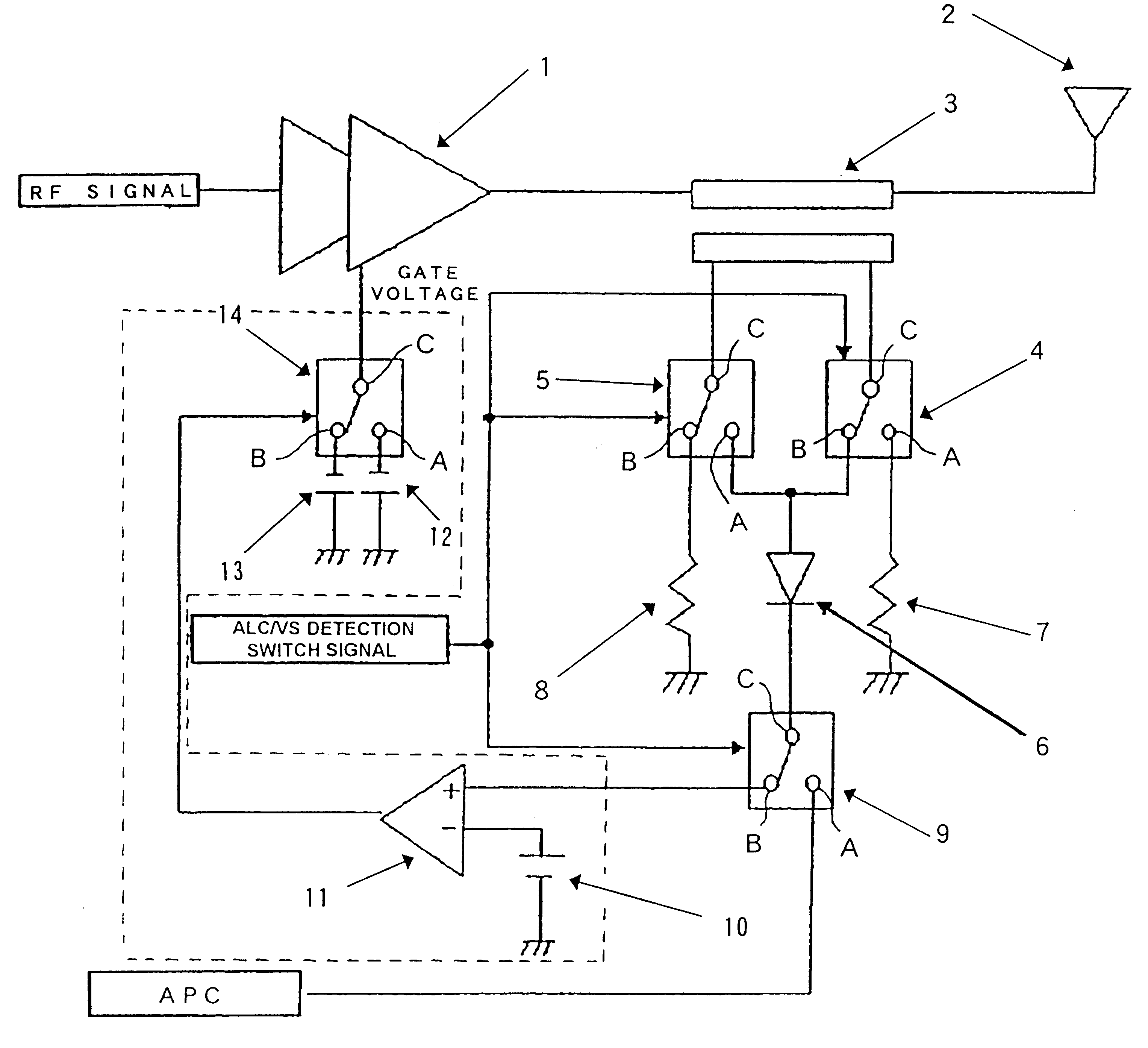
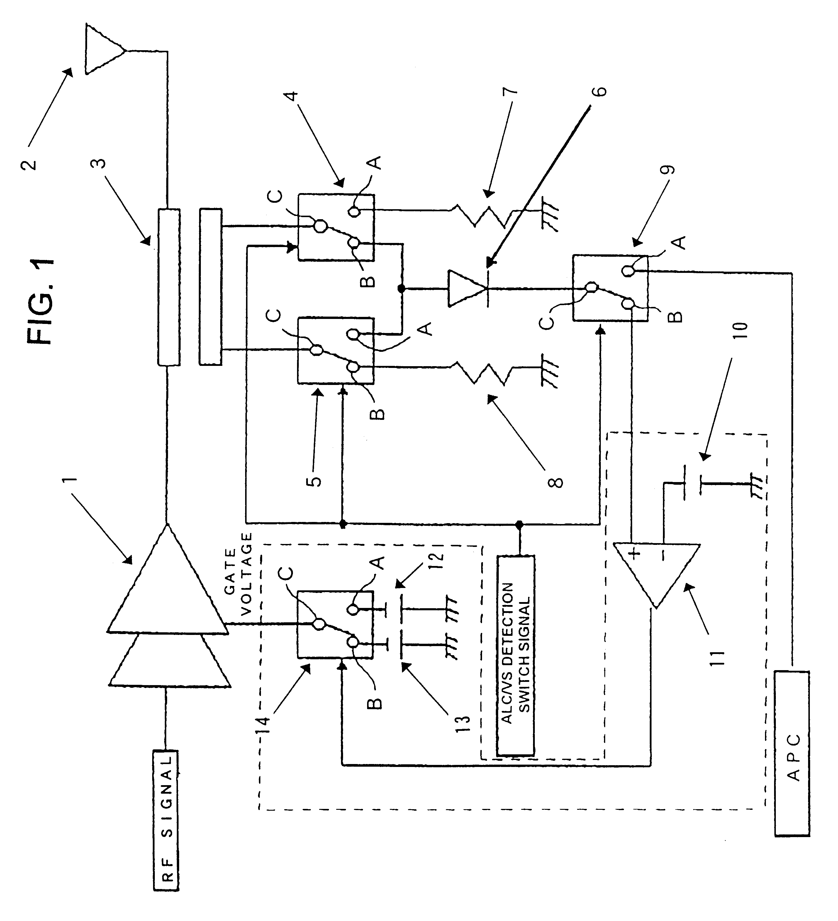
FIG. 1 is a block diagram showing the constitution of a first embodiment of a transmitting circuit according to this invention. In FIG. 1, a radio frequency signal is inputted into a final stage amplifier 1 mainly consisting of a transistor.

This radio frequency (RF) signal is amplified by the final stage amplifier 1 to a specified transmission output. A plurality of optimum gate voltages are applied to the gate of the final stage amplifier 1.

By being applied with the optimum gate voltages, the final stage amplifier 1 can function as a amplifier capable of controlling consumption power and output distortion.

The output terminal of the final stage amplifier 1 is connected to an antenna 2 through a directional coupler 3. The directional coupler 3 has a terminal capable of detecting output power outputted from the final stage amplifier 1 and a terminal capable of detecting a reflected wave generated by the mismatching between the output impedance of the final stage amplifier 1 and a load...


PUM


Abstract

An object of the present invention is to allow the miniaturization of a mobile communication equipment and the reduction of consumption power, and to improve the electrical characteristics of a final stage amplifier. An inputted RF signal is amplified to a specified transmission output by a final stage amplifier, the output power and a reflected wave generated by mismatching between an output impedance of the final stage amplifier and a load impedance connected to an output side of the final stage amplifier are detected by a directional coupler. Two switches are selectively switched in a time division manner, a DC voltage corresponding to the reflected wave is selected, a comparator compares a threshold voltage with the DC voltage, a switch is switched by an output of the comparator outputted in accordance with the comparison, and gate voltages are selectively applied to the final stage amplifier.

Description

1. Technical Field of the InventionThis invention relates to a transmitting circuit for a mobile communication equipment having an automatic output power control circuit (APC), and particularly relates to a transmitting circuit having a directional coupler capable of detecting power outputted from a final stage amplifier and a reflected wave generated by the mismatching between the output impedance of the final stage amplifier and a load impedance connected to the output side of the final stage amplifier, and allowing the gate voltage of the final stage amplifier to be switched depending on the amplitude of this reflected wave.2. Description of the Prior ArtAs a radio frequency power amplifier used in the transmitting circuit of a conventional transmitter, Japanese Patent Application Laid-Open No. 57-118412, for example, discloses a radio frequency power amplifier wherein reflected power from the load of variable gain power amplification means of which gain varies with an external c...

Claims


Application Information

Patent Timeline
Patent Type & Authority Patents(United States)
IPC IPC(8): H03F1/02H03F1/56H03F1/00H03G3/30
CPCH03F1/0261H03F1/56
Inventor AKIYA, MAKOTO
Owner NEC CORP
Why Eureka
Try Eureka