Positioning means for a fibre optic connector assembly, a fibre optic connector assembly and fibre termination unit

A technology of connector components and positioning devices, applied in the direction of optical components, coupling of optical waveguides, fiber mechanical structures, etc.

Inactive Publication Date: 2012-08-22
TYCO ELECTRONICS RAYCHEM BVBA
View PDF8 Cites 0 Cited by
  • Summary
  • Abstract
  • Description
  • Claims
  • Application Information

AI Technical Summary

Problems solved by technology

However, the aforementioned fiber optic connector assemblies also have problems as previously described

Method used


Image

  • Positioning means for a fibre optic connector assembly, a fibre optic connector assembly and fibre termination unit
  • Positioning means for a fibre optic connector assembly, a fibre optic connector assembly and fibre termination unit
  • Positioning means for a fibre optic connector assembly, a fibre optic connector assembly and fibre termination unit

Examples


Embodiment Construction

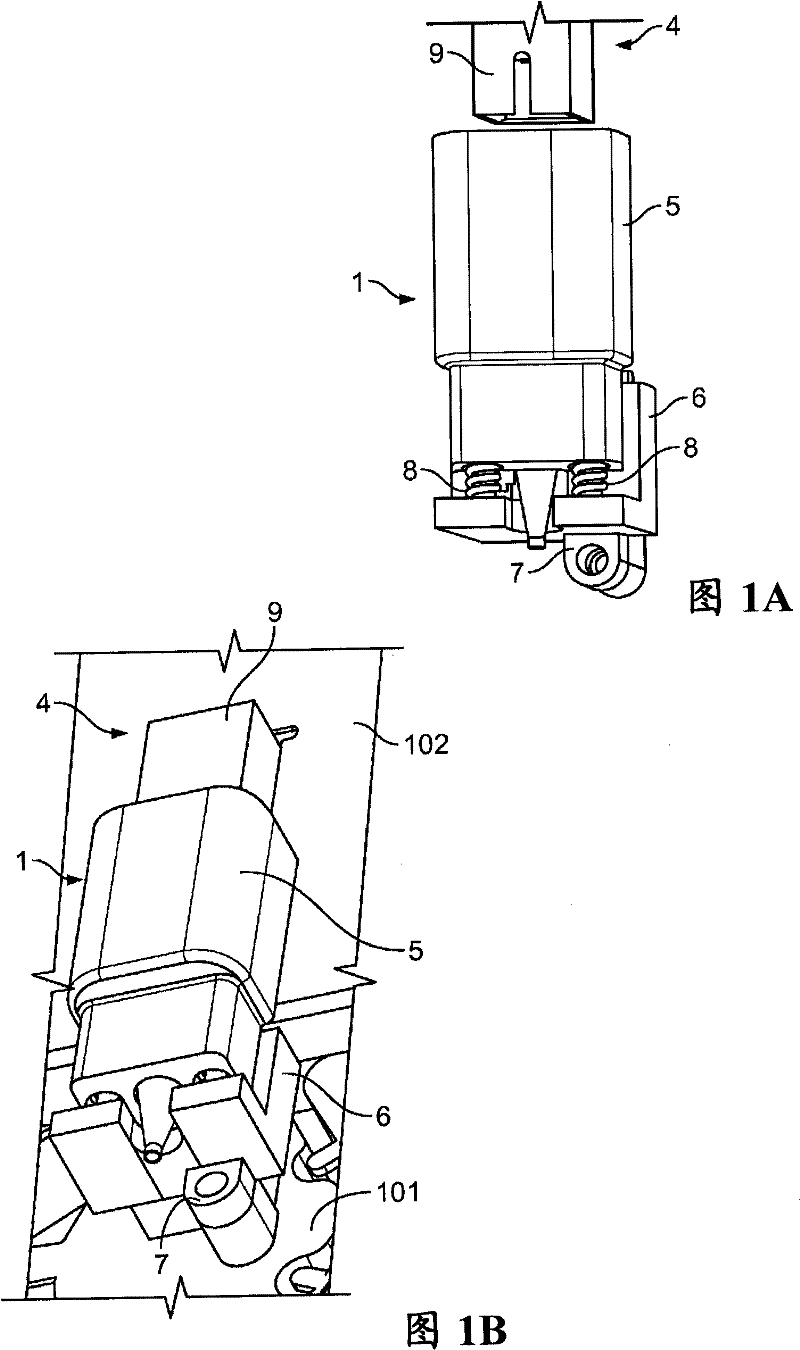
[0027] Figure 1A is a perspective top view of a fiber optic connector assembly comprising a positioning device according to an embodiment in a pre-assembled state, and Figure 1B Shown is a fiber optic connector assembly including the positioning device in an assembled state. The optical fiber connector assembly includes a positioning device 1 (hereinafter the positioning device 1 is marked as a first positioning device 1 ) and a second positioning device 4 opposite to the first positioning device 1 . In a preferred embodiment, the first positioning means 1 is adapted to receive a plug assembly 2 receiving a plug ferrule 3 accessible from one side thereof, and the second positioning means 4 is arranged to receive a socket assembly, the socket The assembly receives a socket ferrule which can be connected to the plug ferrule 3 from the accessible side of the plug ferrule 3 by the connection of the first positioning means 1 and the second positioning means 4 . Alternatively, th...


PUM


Abstract

The present invention relates to a positioning means for a fibre optic connector assembly, a fibre optic connector assembly and a fibre termination unit comprising the positioning means through which manufacturing tolerances can be absorbed to provide an improved optical interconnection with a high signal transmission rate. The positioning means (1) comprises a receiving means (5) for receiving one of a jack assembly or plug assembly (2) and a stationary support (6) supporting said receiving means (5), wherein the receiving means (5) is displaceable to a certain extent relative to the stationary support (6) at least along one direction other than a connection direction for optically interconnecting the optical fibers allowing an alignment of the receivable jack or plug assembly (2) along the direction transversal to the connection direction. A spring loaded element (8) resiliently urges said receiving means (5) away from the support (6) in one embodiment.

Description

technical field [0001] The present invention relates to positioning devices for fiber optic connector assemblies, fiber optic connector assemblies and fiber termination units for use primarily in the technical field of broadband network architectures in which optical fibers replace at least Metal circuit (loop) parts. Background technique [0002] In the last mile telecommunication, an interface such as Fiber Termination Unit (FTU) is needed between the provider side and the client side to convert the optical signal received from the provider side transmit it to the client side and vice versa. The interface typically includes a panel or motherboard that receives the optical fibers to provide a first fiber optic connection and a circuit board secured to the panel or motherboard and to provide a second fiber optic connection that connects to the parts are connected to said first fiber optic connection parts for optically interconnecting the fiber optic elements respectively ...

Claims


Application Information

Patent Timeline
IPC IPC(8): G02B6/38G02B6/44
CPCG02B6/3821G02B6/3825G02B6/3849G02B6/3893G02B6/4439G02B6/3897
Inventor K·瓦斯特曼斯E·舒尔曼斯K·贝勒肯斯
Owner TYCO ELECTRONICS RAYCHEM BVBA
Why Eureka
Try Eureka