Optical ring interconnect

a technology of optical rings and interconnections, applied in the field of optical network communications, can solve the problems of large number of wavelength specific devices that must be manufactured, increase interconnection problems, and complex systems, and achieve the effect of improving wavelength conversion and improving optical interconnections

Inactive Publication Date: 2005-06-28
ALCATEL LUCENT CANADA +1
View PDF5 Cites 9 Cited by
  • Summary
  • Abstract
  • Description
  • Claims
  • Application Information

AI Technical Summary

Benefits of technology

[0009]It is therefore an object of the present invention to overcome the aforementioned disadvantages of the prior art. Accordingly, apparatuses are provided for improved optical interconnects and improved wavelength conversion.

Problems solved by technology

It is a common demultiplexing problem in optical systems to have an optical signal containing multiple wavelengths each at a different wavelength from which one or more individual channels must be extracted.
This same problem exists on the multiplexing side, namely that a large number of wavelength specific devices must be manufactured and inventoried in order to provide multiplexing flexibility.
As these rings become larger and carry more traffic, interconnection issues increase.
Such direct coupling (OOO) of optical rings leads to systems with enormous complexity.
To overcome color blocking, wavelengths cannot be reused locally within each ring therefore link engineering becomes very complex.
Recently, all-optical (OOO) wavelength conversion technology has been developed but such technology is not yet cost-effective.
To control costs, such wavelength converters often use fixed filters, with the attendant disadvantage of the many indirect costs associated with network planning, down time due to reconfigurations, inventory along the value chain and sparing.
Fixed filters also have the disadvantage of increasing the variants of components in a network and this drives up inventory levels because each variant needs to be stocked individually.

Method used


Image

  • Optical ring interconnect
  • Optical ring interconnect
  • Optical ring interconnect

Examples


Embodiment Construction

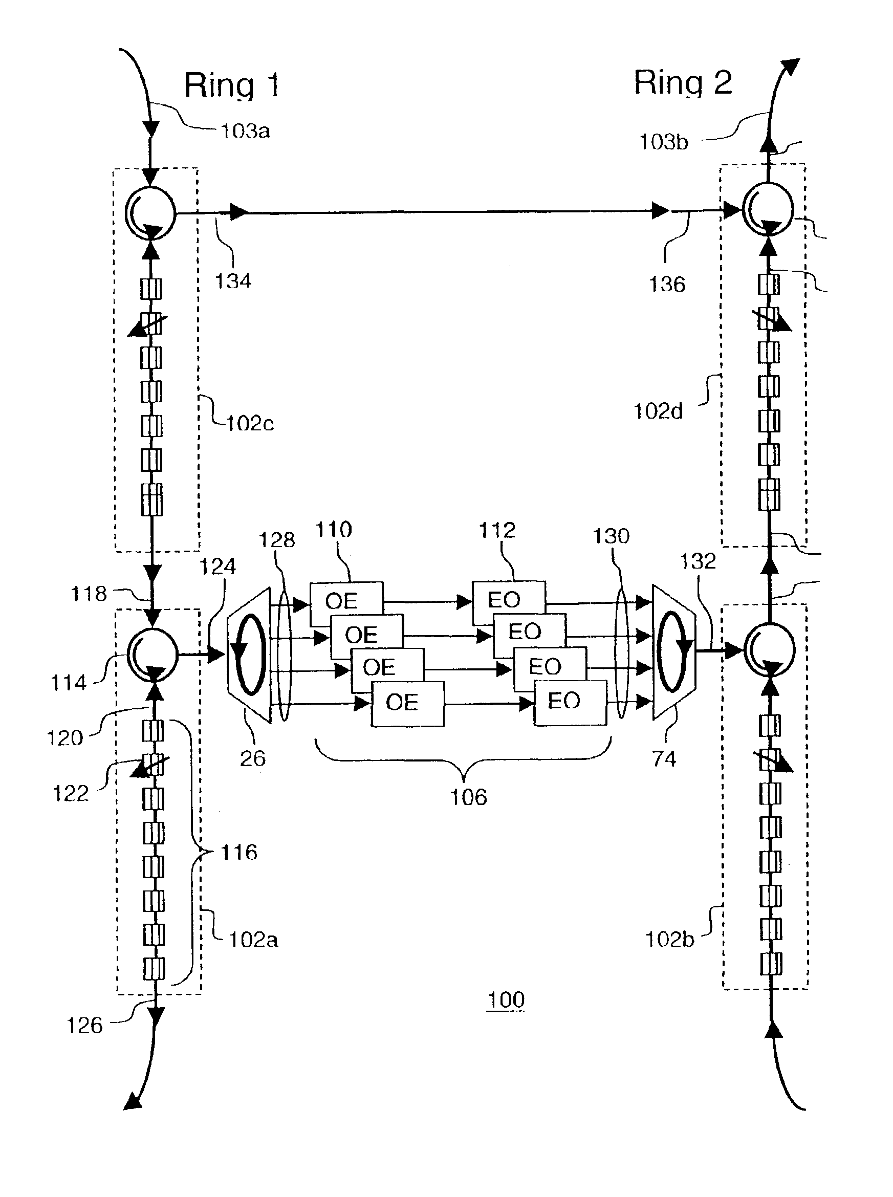
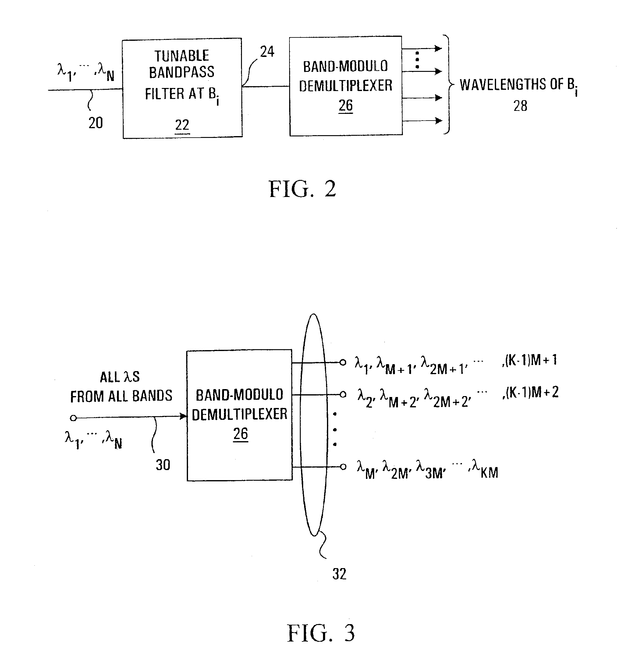
[0047]Referring now to FIG. 2, shown is a block diagram of a demultiplexer according to an embodiment of an aspect of the invention. The demultiplexer has an input optical transmission medium 20 adapted to contain a multi-band optical signal containing multiple wavelengths, λ1, . . . , λN. For example, there might be N=64 different wavelengths. The input optical transmission medium is connected to a tuneable bandpass filter 22, the output 24 of which is connected to a band-modulo demultiplexer 26.

[0048]The input wavelengths λ1, . . . , λN are logically divided into K bands B1, . . . , BK each containing M=N / K consecutive wavelengths of the input wavelengths λ1, . . . , λN. For example, for the N=64 wavelength embodiment, M might be four in which case there are K=64 / 4=16 bands of wavelengths, the first of which is B1=λ1, . . . λ4, the second of which is B2=λ5, . . . λ8, and the last of which is B16=λ61, . . . λ64. The tuneable bandpass filter 22 has a passband equal in width to the b...


PUM


Abstract

Optical interconnects and methods for wavelength management are provided to interconnect optical rings while overcoming color-blocking and allowing for wavelength re-use within optical rings. The optical inter-connects having a wavelength selective element such as a reconfigurable add / drop demultiplexer (ROADM) and a band-modulo demultiplexer having a free spectral range (FSR) combined with a pool of wavelength conversion resources. More flexible interconnect systems can use a photonic cross-connect (PXC) to allow sharing of a pool of wavelength conversion resources among several optical rings.

Description

RELATED APPLICATIONS[0001]This application is a Continuation-In-Part application of, and claims the benefit of U.S. patent application Ser. No. 10 / 259,597 to Bacque et al., filed on Sep. 30, 2002 now U.S. Pat. No. 6,754,413, and entitled “Optical Multiplexer, Demultiplexer and Methods”;[0002]This application also is a continuation-in-part and claims the benefit of U.S. patent application Ser. No. 09 / 839,487 to Bacque et al, filed on Apr. 23, 2001 now abandoned, and entitled “Optical Multiplexer, Demultiplexer and Methods; and[0003]This application also claims the benefit of U.S. Provisional Application Ser. No. 60 / 402,927 to Bacque et al, filed on Aug. 14, 2002, and entitled “Ring Interconnect Using Reconfigurable Optical Add / Drop Multipliers”.FIELD OF THE INVENTION[0004]The invention relates to optical network communications. More particularly, the invention relates to apparatuses for interconnecting optical fibers and optical rings carrying multi-channel optical signals.BACKGROUND...

Claims


Application Information

Patent Timeline
Patent Type & Authority Patents(United States)
IPC IPC(8): H04J14/02G02B6/34
CPCG02B6/29317G02B6/29382H04J14/02G02B6/29395G02B6/29386
Inventor BACQUE, JAMES BENSON
Owner ALCATEL LUCENT CANADA
Why Eureka
Try Eureka