Supercharge Your Innovation With Domain-Expert AI Agents!

Anti-collision sliding door

A sliding door and anti-collision technology, applied in the field of sliding doors, can solve the problems of metal door body deformation, difficult to drive, heavy door body, etc., and achieve the effect of high anti-collision level, preventing door body deformation and reducing deformation.

Active Publication Date: 2015-04-01
ZHANGJIAGANG GOLDNET FENCING SYST
View PDF8 Cites 0 Cited by
  • Summary
  • Abstract
  • Description
  • Claims
  • Application Information

AI Technical Summary

Problems solved by technology

[0002] Generally speaking, the doors used to block the entrance passages of industrial places are usually divided into tracked translation doors and trackless translation doors, and trackless translation doors can be applied to most general For the application of industrial places, for some places with high security level, it is necessary to consider the existence of violent intrusion, especially the possible use of vehicles to forcefully enter the place. In this case, the trackless translation door has few supporting points. , it is easy to be deformed and damaged after being stressed, so it is not applicable; and the railed translation door, due to the limitation of the lower track, can quickly transfer the external force to the track after receiving an external force hitting the door body, so the ability to resist external force is better. However, in order to resist the destructive force of the vehicle, the existing door structure of the sliding door still has many disadvantages
The door body of common anti-collision door or explosion-proof door is usually an integral door formed by filling concrete inside the metal door body, such as Chinese patent 201020153740.6, the door body is very thick and difficult to drive, and the metal door body deforms after being hit. And the internal structure is damaged, it is difficult to repair, only the whole door body can be replaced

Method used


Image

  • Anti-collision sliding door
  • Anti-collision sliding door
  • Anti-collision sliding door

Examples


Embodiment Construction

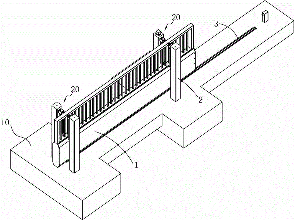
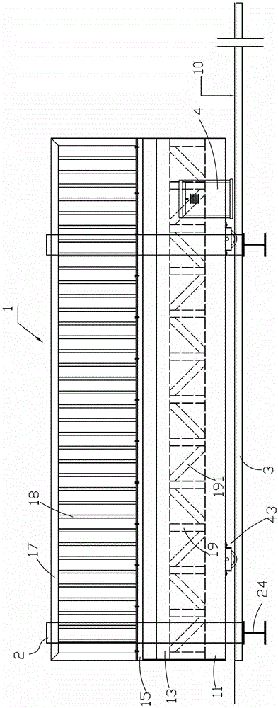
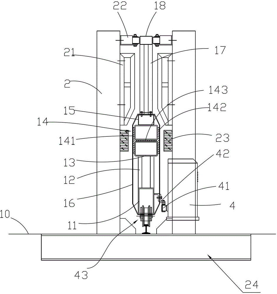
[0028] The present invention will be described in detail below in conjunction with the accompanying drawings, wherein the "front" mentioned in the description refers to the attached figure 2 On the left side of the manual, the "rear" mentioned in the manual refers to the attached figure 2 On the right side of the manual, the "horizontal" direction in the manual refers to the attached figure 2 In the left and right direction, the "longitudinal" direction refers to the attached figure 2 In the up and down direction, the "inner" side mentioned in the manual refers to the attached image 3 The right side in the manual, the "outside" mentioned in the instructions refers to the attached image 3 in the left side.

[0029] as attached figure 1 As shown, an anti-collision sliding door is used to protect the entrance and exit passages of the building enclosure. The passage is defined by a pair of restricting devices 20 arranged in the transverse direction, and the are...


PUM


Abstract

The invention discloses an anti-collision sliding door which is used for protection at a passageway of the enclosure of a building. The passageway is defined by a pair of limiting devices which are arranged in the transversal direction. The sliding door comprises a door body, a guide rail and a driving device. The door body horizontally moves between the two limiting devices and is used for blocking the passageway; the guide rail is paved on the ground and extends along the transverse direction; the driving device drives the door body to move horizontally along the guide rail; and a wheel set connected to the guide rail in rolling fit is arranged below the door body in a rotary manner. The anti-collision sliding door is characterized in that the door body comprises a base beam, a transverse beam and a plurality of longitudinal beams; the base beam and the transverse beam extend in the transverse direction and the longitudinal beams are connected with the base beam and the transverse beam; the outer sides of the base beam and the transverse beam are covered by protective covers. When the anti-collision sliding door is closed, part of the front end of the door body is inserted into the limiting device at the front side of the passageway; and part of the rear end of the door body is inserted into the limiting device at the back side of the passageway.

Description

technical field [0001] The invention relates to a translation door for blocking entrances and exits of building enclosures, in particular to a translation door with an anti-collision structure. Background technique [0002] Generally speaking, the doors used to block the entrance passage of industrial places are usually divided into tracked translation doors and trackless translation doors. Trackless translation doors can be applied to most general industrial places, and for some places with high security level , it is necessary to consider the existence of violent intrusion, especially the possible use of vehicles to forcefully enter the site. In this case, the trackless translational door is not applicable due to the lack of support points and is easily deformed and damaged after being stressed; Due to the limitation of the lower track, the translation door can quickly transfer the external force to the track after receiving an external force hitting the door body, so the ...

Claims


Application Information

Patent Timeline
Patent Type & Authority Patents(China)
IPC IPC(8): E06B11/02E05F5/06
Inventor 宋国华徐律吴海
Owner ZHANGJIAGANG GOLDNET FENCING SYST
Features
  • R&D
  • Intellectual Property
  • Life Sciences
  • Materials
  • Tech Scout
  • Unparalleled Data Quality
  • Higher Quality Content
  • 60% Fewer Hallucinations
Learn More