Battery pack and system of battery pack

A battery pack, battery technology, applied in battery circuit devices, current collectors, electric vehicles, etc., can solve the problems of short service life, poor performance, poor safety performance, etc., to improve safety performance and service life, avoid mutual interference, The effect of convenient post-maintenance

Inactive Publication Date: 2012-08-29
陈明军
View PDF3 Cites 5 Cited by
  • Summary
  • Abstract
  • Description
  • Claims
  • Application Information

AI Technical Summary

Problems solved by technology

[0003] In the prior art, the power of new energy vehicles is mainly provided by battery packs. Most of the battery pack schemes use the method of paralleling first and then series. Although this method can make the cost of the protection circuit and equalization circuit of the battery pack lower, However, the safety performance is poor. If there is a battery with poor performance in the parallel battery pack, the performance of the entire battery pack will deteriorate. If one battery in the battery pack is broken, other batteries will form a reverse charge for it. state, and the broken battery itself is not fully charged, so the temperature of the broken battery will inevitably rise or even explode, which will have a bad impact on other batteries
Therefore, the safety performance of the whole battery pack is poor and the service life is short
Secondly, in terms of cost, power battery packs that are connected in parallel first and then connected in series generally can only play 75% to 80% of the total capacity, and need to provide more power, which can only increase the number of batteries, which increases the cost instead.

Method used


Image

  • Battery pack and system of battery pack
  • Battery pack and system of battery pack
  • Battery pack and system of battery pack

Examples


Embodiment Construction

[0026] The technical solutions in the embodiments of the present invention will be clearly and completely described below with reference to the accompanying drawings in the embodiments of the present invention. Obviously, the described embodiments are only a part of the embodiments of the present invention, but not all of the embodiments. Based on the embodiments of the present invention, all other embodiments obtained by those of ordinary skill in the art without creative efforts shall fall within the protection scope of the present invention.

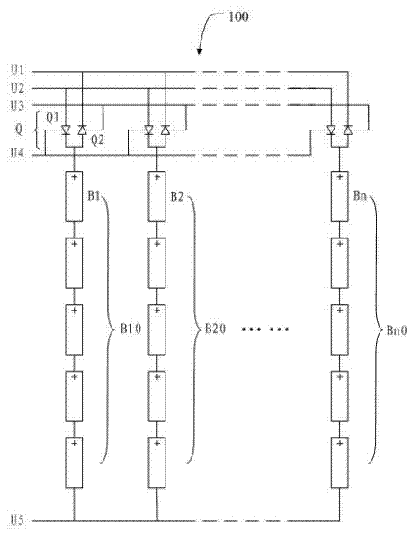
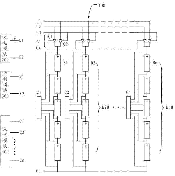
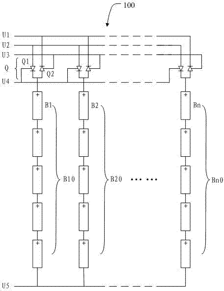
[0027] see figure 1 , is a schematic diagram of the composition of the battery pack 100 of the present invention. The battery pack 100 includes a plurality of battery groups B10 and B20 up to Bn0 , a charging circuit U2 , a discharging circuit U1 , a control circuit U0 (not shown) and a switch circuit Q.

[0028] The battery group B10 is composed of a plurality of batteries B1 in series in series, correspondingly, the battery group B...


PUM


Abstract

The embodiment of the invention discloses a battery pack, which comprises a plurality of small battery packs, a charging circuit, a discharging circuit and a control circuit, wherein each small battery pack is formed by sequentially and serially connecting a plurality of batteries, and the small battery packs are connected in parallel; a positive electrode of the charging circuit is electrically connected with a positive electrode of each small battery pack, and a negative electrode of the charging circuit is electrically connected with a negative electrode of each small battery pack; a positive electrode of the discharging circuit is electrically connected with the positive electrode of each small battery pack, and a negative electrode of the discharging circuit is electrically connected with the negative electrode of each small battery pack; the control circuit comprises a charging control circuit and a discharging control circuit, the charging control circuit is electrically connected with the charging circuit, and the discharging control circuit is electrically connected with the discharging circuit. The embodiment of the invention also discloses a battery pack system. When the battery pack and the battery pack system are adopted, the safety performance during the battery pack operation can be improved, and the service life of the battery pack can be prolonged.

Description

technical field [0001] The invention relates to the field of energy, in particular to a battery pack and a system thereof. Background technique [0002] The "Administrative Rules for the Access of New Energy Vehicle Manufacturers and Products" has been officially implemented on July 1, 2009, which emphasizes that: New energy vehicles refer to the use of unconventional vehicle fuels as power sources (or the use of conventional vehicle fuels). Fuel, the use of new vehicle-mounted power units), integrated advanced technology in vehicle power control and drive, the formation of advanced technical principles, with new technology, new structure of the car. [0003] In the prior art, the power of the new energy vehicle is mainly provided by the battery pack. Most battery pack solutions adopt the method of paralleling first and then series. Although this method can make the cost of the protection circuit and balancing circuit of the battery pack lower, However, the safety performan...

Claims


Application Information

Patent Timeline
Patent Type & Authority Applications(China)
IPC IPC(8): H02J7/00
Inventor 陈明军
Owner 陈明军
Why Eureka
Try Eureka