
Device and method for testing wafer

A wafer testing and wafer technology, applied in the direction of semiconductor/solid state device testing/measurement, etc., can solve the problems of loop oscillation, influence of measurement probe accuracy, and probe card leakage.

Active Publication Date: 2014-12-31
WUXI ZGMICRO ELECTRONICS CO LTD
View PDF6 Cites 0 Cited by
  • Summary
  • Abstract
  • Description
  • Claims
  • Application Information

AI Technical Summary

Problems solved by technology

[0005] In the process of realizing the present invention, the inventors have found that the prior art has at least the following defects: First, the probe cards in the prior art usually have electric leakage, and when using the probe card including electric leakage for testing, if these electric leakage On the low-impedance node of the chip (such as the node driving ability is very strong), it has little effect on the circuit in the chip
Second, it is easy to generate parasitic capacitance between the probe and the chip, and the parasitic capacitance also has a certain influence on the accuracy of the measurement probe, and may even cause loop oscillation

Method used


Image

  • Device and method for testing wafer
  • Device and method for testing wafer

Examples


Embodiment Construction

[0024] The detailed description of the present invention directly or indirectly simulates the operation of the technical solution of the present invention mainly through programs, steps, logic blocks, processes or other symbolic descriptions. In the ensuing description, numerous specific details are set forth in order to provide a thorough understanding of the present invention. Rather, the invention may be practiced without these specific details. These descriptions and representations herein are used by those skilled in the art to effectively convey the substance of their work to others skilled in the art. In other words, for the purpose of avoiding obscuring the present invention, well-known methods, procedures, components and circuits have not been described in detail since they are readily understood.

[0025] Reference herein to "one embodiment" or "an embodiment" refers to a particular feature, structure or characteristic that can be included in at least one implementa...


PUM


Abstract

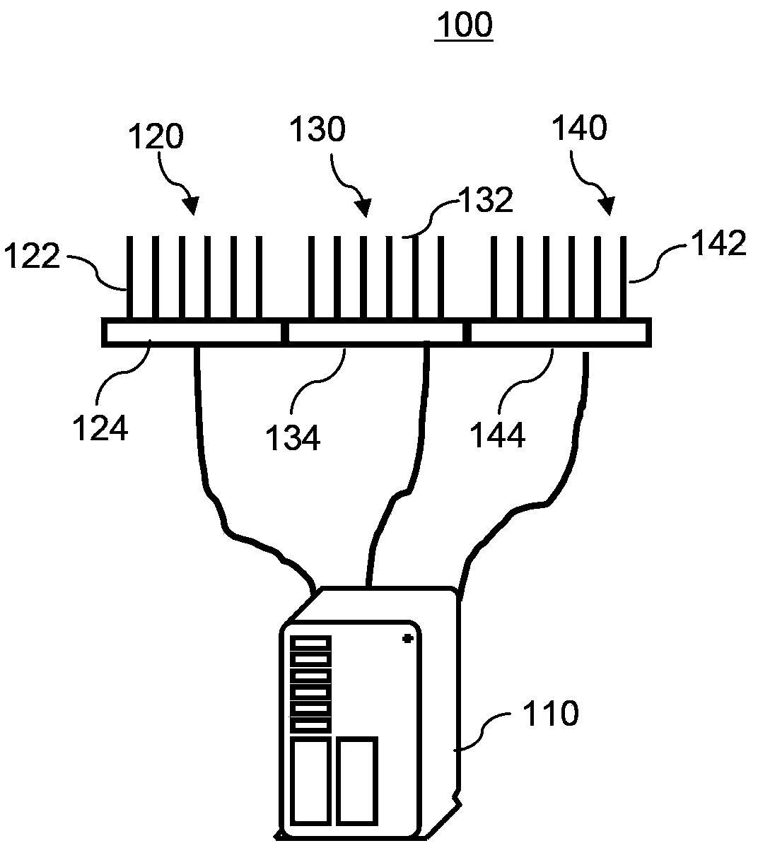
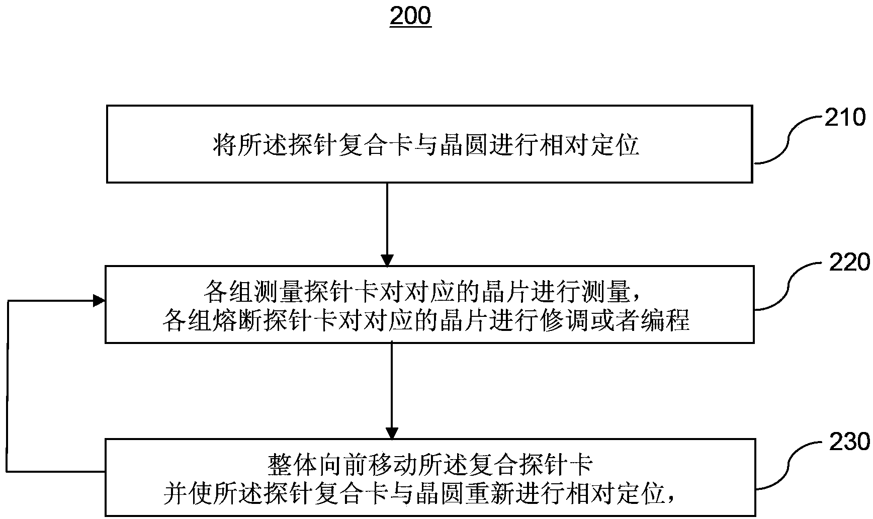
The invention discloses a device and a method for testing wafers. The wafer testing device comprises a set of composite probe cards, wherein the composite probe cards comprise at least one group of measurement probe cards, and the measurement probe cards comprise measurement probes used for measuring electrical signals of corresponding wafers and at least one group of fusing probe cards; the fusing probe cards comprise fusing probes used for trimming or programming corresponding wafers; when the composite probe cards are placed at the same position, various groups of probe cards respectively correspond to different wafers, so that during wafer testing, a measurement process and a fusing process of the same wafer are separately carried out, and the measurement precision is improved; moreover, because the measurement processes and the fusing processes of different wafers can be simultaneously carried out, occupied time of a testing machine is never prolonged excessively, and testing cost is proportional to testing time; and according to the device and the method, the measurement precision is improved, but the testing cost is never increased excessively.

Description

【Technical field】 [0001] The invention relates to the field of wafer testing, in particular to a wafer testing device and method. 【Background technique】 [0002] In the chip manufacturing process, it can be divided into four major steps: IC design, wafer manufacturing process, wafer testing and wafer packaging. [0003] Wafers are usually circular silicon wafers with diameters of 4 inches, 6 inches, 8 inches, and 12 inches. In the wafer process stage, a large number of chips that are tightly and regularly distributed will be formed on the wafer. Depending on the size of the wafer, there may be hundreds to hundreds of thousands of chips on a wafer. In the wafer test stage, a test environment is usually built by the test machine and the probe card, and the chips on the wafer are tested in this environment to ensure that the electrical characteristics and functions of each chip meet the design specifications and specifications. . Wafers that fail the test will be marked as b...

Claims


Application Information

Patent Timeline
Patent Type & Authority Patents(China)
IPC IPC(8): H01L21/66
Inventor 王钊田文博尹航
Owner WUXI ZGMICRO ELECTRONICS CO LTD
Learn More