Touch display device

A technology of touch display and equipment, which is applied in the direction of instruments, electrical digital data processing, and input/output process of data processing, etc. It can solve the problems of thickness, life and stability of infrared touch display devices, difficulty in using infrared touch, etc. problem, to achieve the effect of ultra-narrow frame, long service life and reduced width

Inactive Publication Date: 2012-09-12
SHENZHEN TIMELINK ECHNOLOGY CO LTD
View PDF6 Cites 18 Cited by
  • Summary
  • Abstract
  • Description
  • Claims
  • Application Information

AI Technical Summary

Problems solved by technology

[0005] First, because the printed circuit board used to connect the infrared emitting tube and the infrared receiving tube is embedded around the flat panel display part, and the printed circuit board and the flat panel display part are arranged on the same plane, when packaging the flat panel display part When the outer frame of the type component is used, the outer frame needs to encapsulate the printed circuit board, so the size of the outer frame of the flat panel display component is correspondingly larger, so that the infrared touch display device is very thick;
[0006] Second, in order to make the infrared rays emitted and received by the infrared emitting tube and the infrared receiving tube parallel to the flat panel display components, the infrared emitting tube and the infrared receiving tube need to be bent and then soldered and installed on the printed circuit board, or first Soldering and installing on the printed circuit board, and then bending the feet, not only the process is complicated, but also the manufacturing cost is increased, and the life and stability of the infrared emitting tube and the infrared receiving tube may be affected after bending
As a result, it is difficult to use infrared touch technology on many ultra-thin and ultra-narrow displays

Method used


Image

  • Touch display device
  • Touch display device
  • Touch display device

Examples


Embodiment Construction

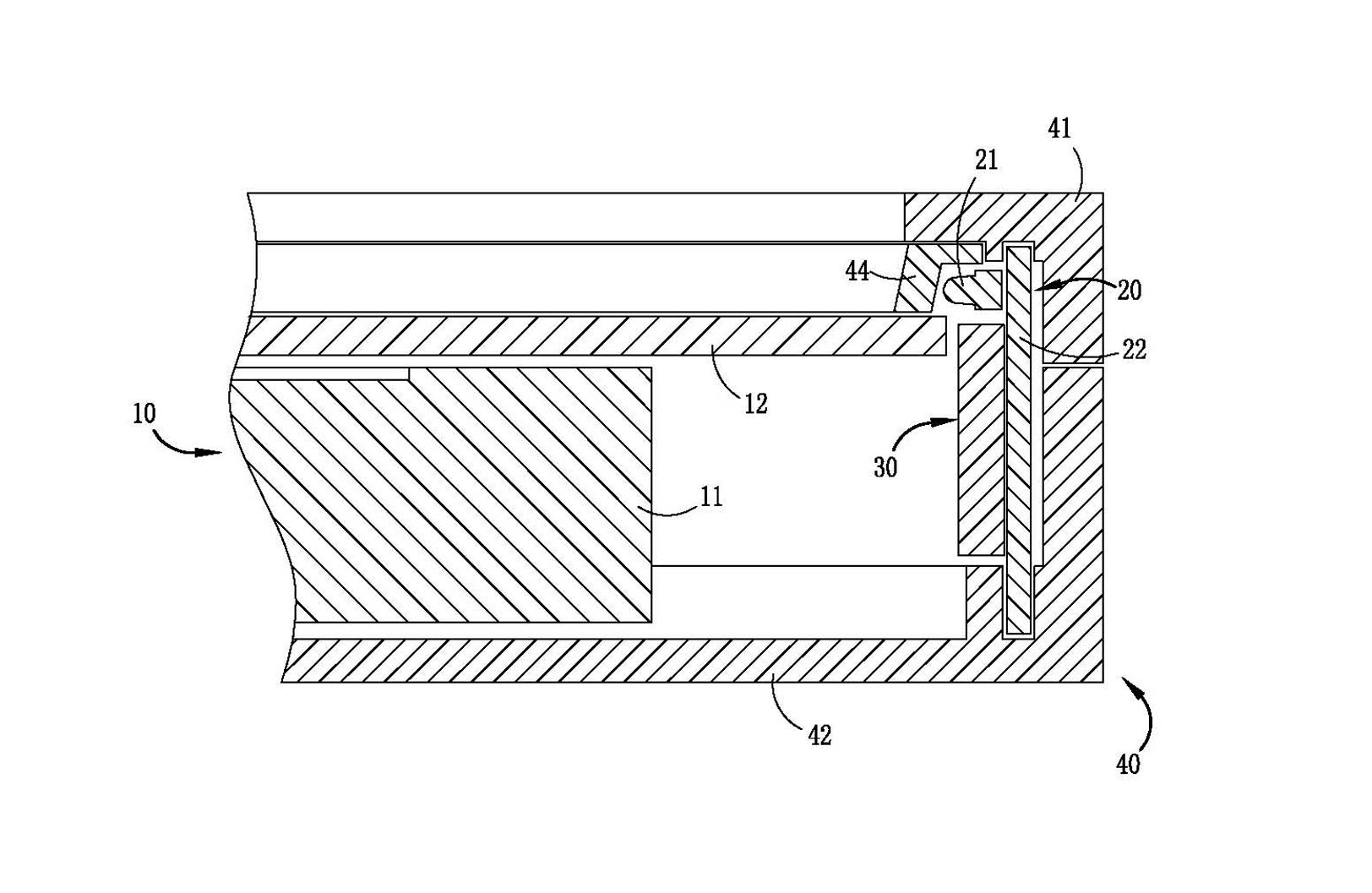
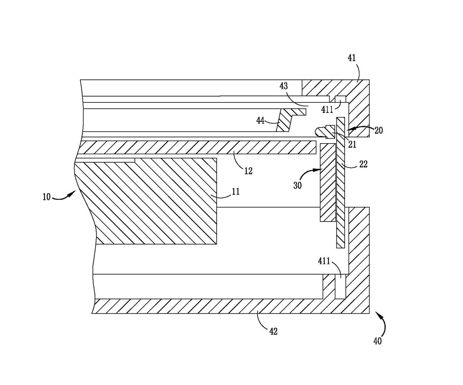
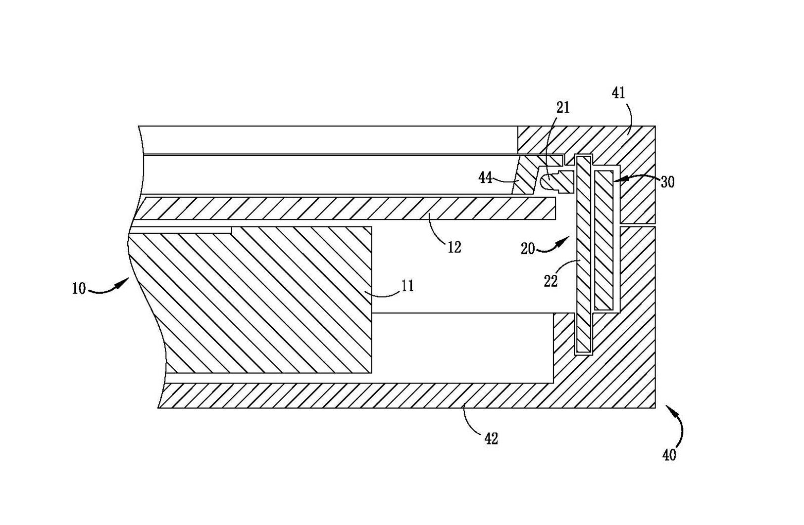
[0024] The following will be combined with Figures 1 to 4 A touch display device proposed by the present invention is described in more detail in the preferred embodiment.

[0025] Such as figure 1 As shown, the present invention provides a touch display device, which includes a flat panel display component 10, a sensing signal transceiving module 20, a control module 30, and an outer casing 40, wherein the sensing signal transceiving module 20 is arranged around the flat panel Around the display part 10, the flat panel display part 10, the induction signal transceiver module 20 and the control module 30 are all packaged in the outer casing 40;

[0026] The flat panel display unit 10 includes a liquid crystal display 11;

[0027] The induction signal transceiver module 20 includes several induction signal transceiver pairs 21 and a printed circuit board 22, and several induction signal transceiver pairs 21 are electrically connected to the printed circuit board 22, and the ...


PUM


Abstract

A touch display device comprises a flat display component, an induction signal transceiving module, a control module and a casing. The induction signal transceiving module is circularly arranged on the periphery of the flat display component, the flat display component, the induction signal transceiving module and the control module are all packaged in the casing, the flat display component comprises a liquid crystal displayer, the induction signal transceiving module comprises a plurality of induction signal transceiving pair pipes and a printed circuit board, and the plurality of induction signal transceiving pair pipes are electrically connected onto the printed circuit board. The induction signal transceiving pair pipes comprise induction signal emitting pipes and induction signal receiving pipes, the printed circuit board is circularly arranged on the periphery of the liquid crystal displayer, the printed circuit board is perpendicular to a liquid crystal displayer panel, and the induction signal transceiving pair pipes electrically connected with the printed circuit board are arranged on the front side of a display surface of the liquid crystal displayer.

Description

technical field [0001] The invention relates to the field of display and touch control, in particular to a touch-sensitive display device. Background technique [0002] For the convenience of operation, when people use a touch screen instead of a mouse or keyboard to work, we must first touch the touch screen installed on the front of the display with fingers or other objects, and then the system locates and selects information according to the icon or menu position touched by the finger. Input the touch screen by It consists of a touch detection component and a touch screen controller; the touch detection component is installed in front of the display screen to detect the user’s touch position and send it to the touch screen controller after receiving it; the main function of the touch screen controller is to receive touch information from the touch point detection device, And convert it into contact coordinates, and then send it to the CPU, and it can receive and execute t...

Claims


Application Information

Patent Timeline
Patent Type & Authority Applications(China)
IPC IPC(8): G06F3/042
CPCG06F3/046
Inventor 陈伟山
Owner SHENZHEN TIMELINK ECHNOLOGY CO LTD
Why Eureka
Try Eureka