
a display panel

A display panel and substrate technology, which is applied in the direction of instruments, nonlinear optics, optics, etc., can solve the problems of GOA circuit occupation, large frame space, etc., and achieve the effect of realizing ultra-narrow frame and improving the effect of occupying a large frame

Active Publication Date: 2022-04-26
TCL CHINA STAR OPTOELECTRONICS TECH CO LTD
View PDF6 Cites 0 Cited by
  • Summary
  • Abstract
  • Description
  • Claims
  • Application Information

AI Technical Summary

Problems solved by technology

[0005] The present application provides a display panel, which solves the problem that the GOA circuit arranged on the array substrate occupies a large frame space

Method used


Image

  • a display panel
  • a display panel
  • a display panel

Examples


Embodiment Construction

[0023] The technical solutions in the embodiments of the present application will be clearly and completely described below in conjunction with the drawings in the embodiments of the present application. Apparently, the described embodiments are only some of the embodiments of this application, not all of them. Based on the embodiments in this application, all other embodiments obtained by those skilled in the art without making creative efforts belong to the scope of protection of this application.

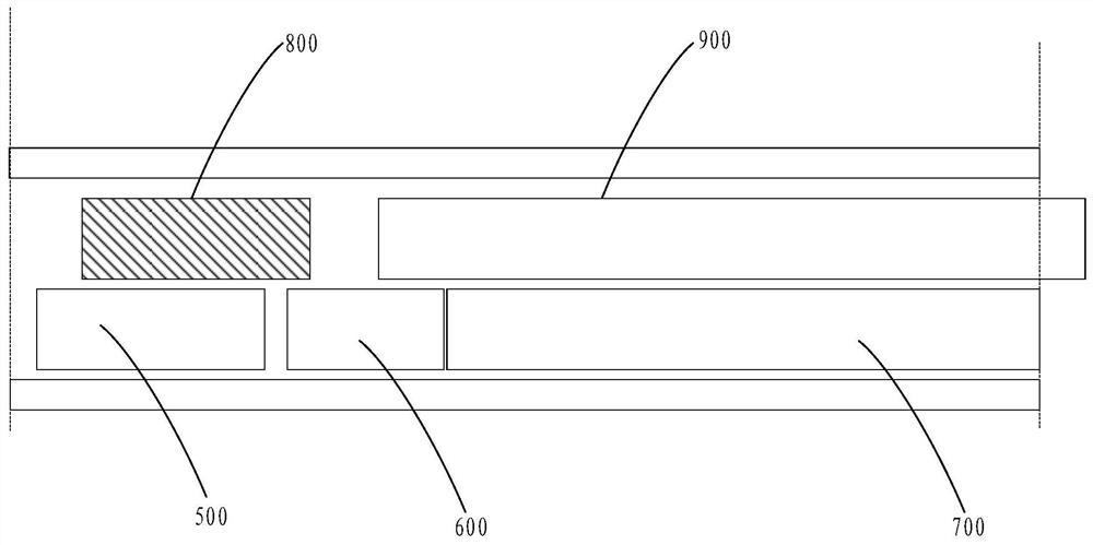
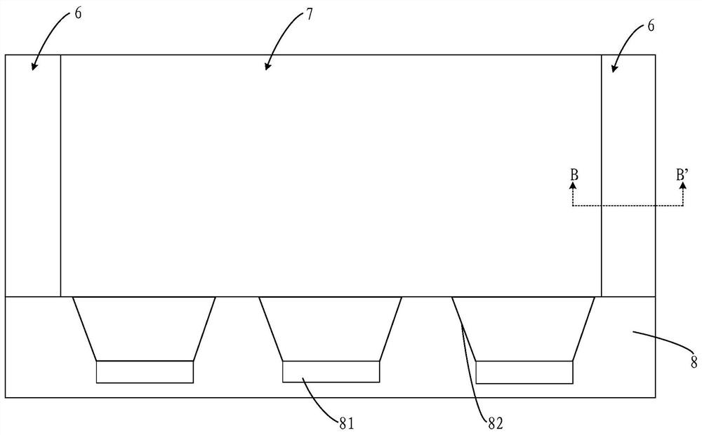
[0024] Such as Figure 2A and Figure 2B As shown, the present embodiment provides a display panel, which includes a lower substrate 2 and an upper substrate 1 that are arranged in a box and bonded by a conductive glue 3, and a liquid crystal located between the lower substrate 2 and the upper substrate 1. layer; the upper substrate 1 is formed with a GOA circuit 4; the lower substrate 2 is formed with a signal line 5; in the light emitting direction of the display panel, the G...


PUM


Abstract

The application discloses a display panel. The display panel includes a lower substrate and an upper substrate that are arranged on the box and bonded by conductive glue; a GOA circuit is formed on the upper substrate; a signal line is formed on the lower substrate; , the GOA circuit is arranged opposite to the signal line, and the GOA circuit is electrically connected to the signal line through conductive glue. The GOA circuit is arranged on the upper substrate, and the GOA circuit is arranged opposite to the signal line, which is beneficial to the realization of an ultra-narrow frame.

Description

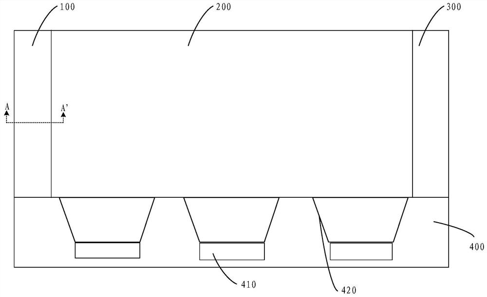
technical field [0001] The present application relates to the field of display technology, in particular to the field of narrow frame display technology, and in particular to a display panel. Background technique [0002] The GOA (Gate Driver on Array, array row drive) technology is beneficial to the design of a narrow frame on the gate driver (gatedriver) side of the display screen, and reduces the cost, and has been widely used and researched. [0003] In response to market demand, large size (Size), high resolution and super narrow border (ENB, Excellent Narrow Border) have become market trends. The resolution becomes higher, the pixel size (Pixel size) shrinks, and the space occupied by the GOA layout (Layout) increases How to achieve narrow bezels has become a difficulty that must be overcome. [0004] Figure 1A It is a schematic diagram of the array substrate side panel (Panel). In order to realize a narrow frame, the GOA circuit is made on the left frame 100 and the...

Claims


Application Information

Patent Timeline
Patent Type & Authority Patents(China)
IPC IPC(8): G02F1/1345G02F1/1362
CPCG02F1/13454G02F1/136286
Inventor 朱静
Owner TCL CHINA STAR OPTOELECTRONICS TECH CO LTD
Learn More