
Mounting structure of amorphous alloy transformer

An amorphous alloy and installation structure technology, applied in the field of transformers, can solve the problems of time-consuming assembly and low accuracy of the box cover, and achieve the effect of avoiding iron core fragments and avoiding the increase of no-load loss.

Active Publication Date: 2012-09-12
SHANGHAI ZHIXIN ELECTRIC AMORPHOUS +4
View PDF6 Cites 2 Cited by
  • Summary
  • Abstract
  • Description
  • Claims
  • Application Information

AI Technical Summary

Problems solved by technology

This structure fixes the body by welding four screws under the cover and the rigid connection of the body. Although the body can be fixed to avoid vibration, but because the thread needs to be adjusted to keep the cover level, the assembly will be time-consuming and the case The lid stays level with less precision

Method used


Image

  • Mounting structure of amorphous alloy transformer
  • Mounting structure of amorphous alloy transformer

Examples


Embodiment Construction

[0012] In order to enable those skilled in the art to better understand the technical solution of the present invention, its specific implementation will be described in detail below in conjunction with the accompanying drawings:

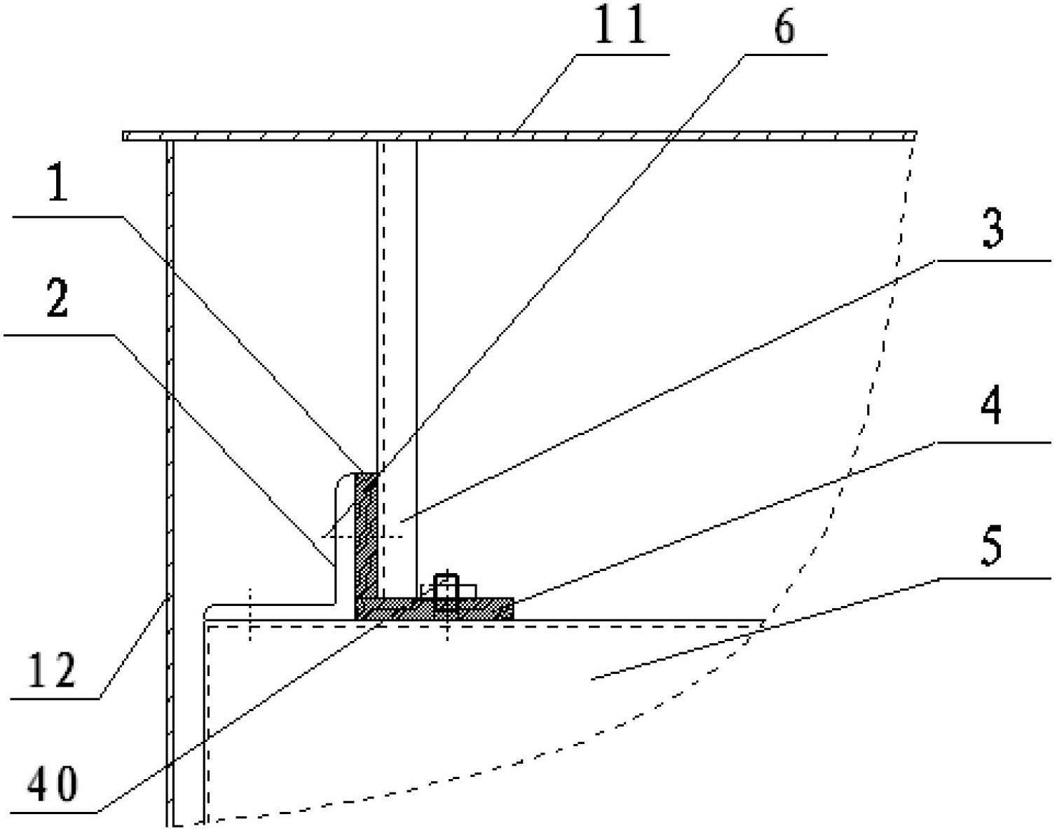
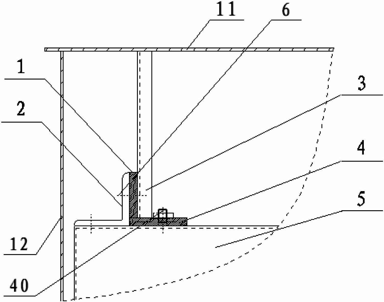
[0013] see figure 1 , the mounting structure of the amorphous alloy transformer of the present invention includes the oil tank of the amorphous alloy transformer and the body of the amorphous alloy transformer, wherein,

[0014] The fuel tank includes a tank cover 11 and a box body 12, and the lower end surface of the tank cover 11 is evenly connected with several fixing plates 3;

[0015] The amorphous alloy transformer is placed in the oil tank through a positioning mechanism arranged at the bottom of the box body 11;

[0016] The body includes an upper clip 5 at the top, and a number of right-angled bridge plates 2 corresponding to the fixed plate 3 are fixed on the top surface of the upper clip 5;

[0017] The lower end surface of each fixed p...


PUM


Abstract

The invention discloses a mounting structure of an amorphous alloy transformer. The mounting structure of the amorphous alloy transformer comprises an oil tank and a transformer body of the amorphous alloy transformer which is arranged in the oil tank and comprises an upper clamp. The oil tank comprises a tank cover and a tank body, a plurality of fixing plates are connected to the upper end face of the tank cover by means of evenly distribution, a plurality of right-angled bridge plates in one-to-one correspondence with the fixing plates are fixed on the top face of the upper clamp, the lower end face of each of the fixing plates butts against the tope face of the upper clamp of the transformer body through a first cushion, and a second cushion is arranged between the side face of each of the fixing plates and a vertical portion of the corresponding bridge plate and is connected to the bridge plate through a connecting piece. By the mounting structure of the amorphous alloy transformer, corresponding vibration of the transformer body due to electromotive force produced by a coil is reduced when the transformer is short-circuited unexpectedly, and no-load loss increasing and core fragments caused by extra-stress produced by vibration of the transformer can be prevented effectively.

Description

technical field [0001] The invention relates to a transformer, in particular to an installation structure of an amorphous alloy transformer. Background technique [0002] There are two installation structures for the traditional amorphous alloy transformer body after it enters the oil tank. One is that the body is positioned by several positioning devices at the bottom of the oil tank and is not fixed. Once the coil suddenly short-circuits in this structure, the body will jump with the vibration of the coil in the fuel tank, and the amorphous alloy iron core in the body will inevitably be impacted to generate additional stress, which will produce iron core fragments , the no-load loss will also increase. Another kind of structure is that the clip connected on the body of the device is connected with the tank cover of the fuel tank by a screw rod, and the height of the body of the regulator entering the fuel tank is adjusted by the threads. This structure fixes the body by ...

Claims


Application Information

Patent Timeline
Patent Type & Authority Applications(China)
IPC IPC(8): H01F27/06H01F27/14H01F27/30
Inventor 蔡煜林雪军杜吉红
Owner SHANGHAI ZHIXIN ELECTRIC AMORPHOUS
Learn More