
Anti-friction bearing having bump-like projections which are attached to the bearing outer ring

A technology for rolling bearings and bearing outer rings, applied in ball bearings, bearing components, shafts and bearings, etc., can solve the problem of high cost, reduce sound radiation, and simplify the manufacturing process.

Inactive Publication Date: 2012-09-12
SCHAEFFLER TECH AG & CO KG
View PDF8 Cites 2 Cited by
  • Summary
  • Abstract
  • Description
  • Claims
  • Application Information

AI Technical Summary

Problems solved by technology

However, a disadvantage arises that, in addition to the radial movability of the rolling bearing, there is also an axial movability due to torsion of the sleeve surrounding the outer ring of the bearing
[0012] The solutions disclosed in DE 10307842A1 are also open to improvement, since they are relatively costly to implement

Method used


Image

  • Anti-friction bearing having bump-like projections which are attached to the bearing outer ring
  • Anti-friction bearing having bump-like projections which are attached to the bearing outer ring
  • Anti-friction bearing having bump-like projections which are attached to the bearing outer ring

Examples


Embodiment Construction

[0038]The drawings are merely schematic in nature and only facilitate the understanding of the invention. For the same elements, the same reference numbers are used.

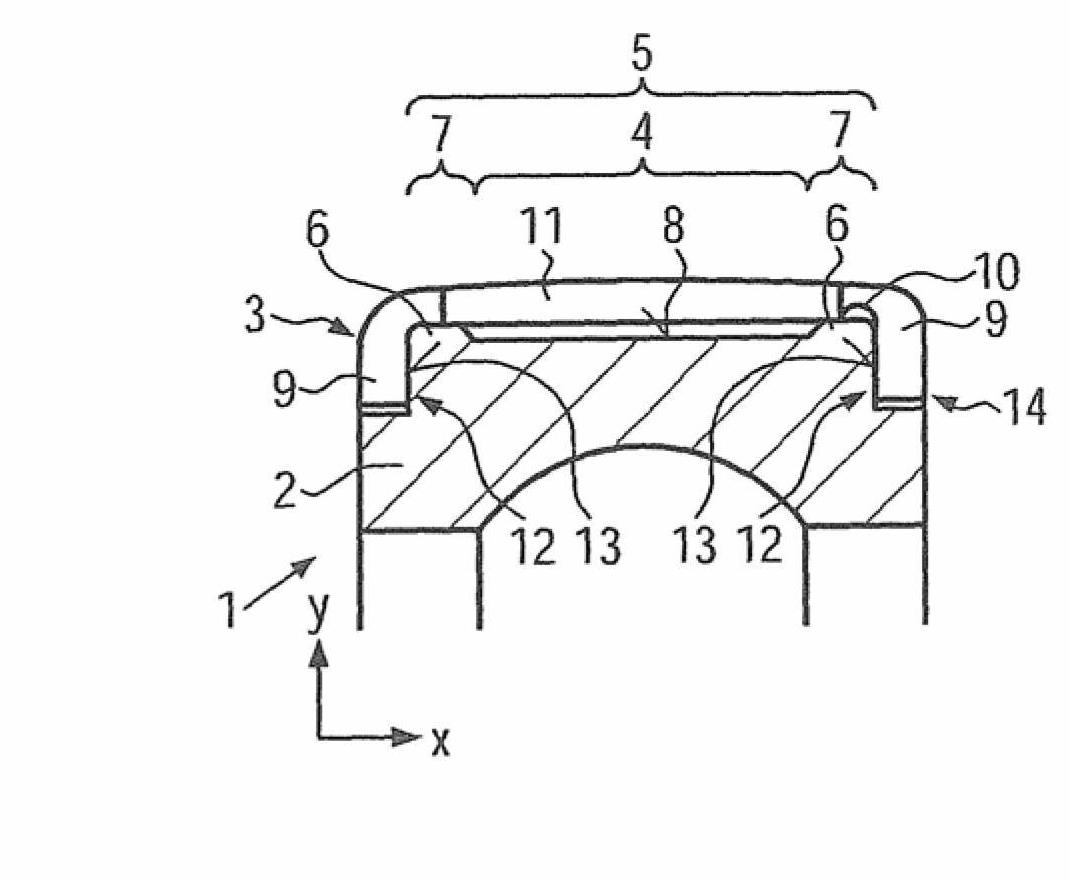
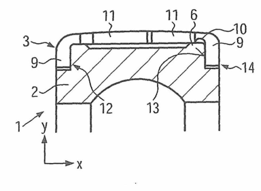
[0039] figure 1 Shown in is a section of a first rolling bearing 1 according to the invention. The bearing inner ring is not shown, likewise the rolling bodies accommodated in the cage. Only the bearing outer ring 2 is shown. Also shown is a separating element 3 arranged radially on the outside of the bearing outer ring 2 . The separating element 3 has an abutment section 5 interrupted by a spring section 4 . The rest section 5 bears against the hump-shaped projection 6 . The boss 6 has a boss surface 7 . The axial length of the bead surface 7 plus the axial length of the spring section 4 equals the axial length of the bearing section 5 . Ultimately, therefore, the contact section 5 bears against the radial circumferential surface 8 of the bearing outer ring 2 only in the region of the bead surface 7 .

...


PUM


Abstract

The invention relates to an anti-friction bearing (1) having a bearing inner ring and a bearing outer ring (2) which is arranged radially outside the former, between which rolling bodies are positioned, wherein there is a single-piece decoupling element (3) radially outside the bearing outer ring (2) as vibration damper which engages around the bearing outer ring (2) at least in sections and rests with a bearing section (4) of at least partially cylindrical design on the outer circumferential surface of the bearing outer ring (2), wherein the bearing section (4) is interrupted in the axial direction by a spring section (5), in which the decoupling element (3) is spaced apart from the outer circumferential surface of the bearing outer ring (2). According to the invention, two bump-like projections (6) which extend at least partially over the circumference and on which the bearing section (4) rests are present on the outer circumferential surface of the bearing outer ring (2).

Description

technical field [0001] The invention relates to a rolling bearing with a bearing inner ring and a bearing outer ring arranged radially outside the bearing inner ring, rolling elements are positioned between the bearing inner ring and the bearing outer ring, wherein the bearing outer ring is radially outside As a vibration damper, there is a one-piece separating element (Abkopplungselement), which surrounds the bearing outer ring at least in sections and bears against the outer shell surface of the bearing outer ring with an at least partially cylindrical contact section. , wherein the contact section is interrupted in the axial direction by a spring section in which the separating element is spaced apart from the outer shell surface of the bearing outer ring. Background technique [0002] Such rolling bearings with elements rolling as rolling bodies are known from the prior art, for example from DE 10 2007 045 671 A1, DE 221 409 A1 or DE 3 041 804 A1. Balls, rollers, roller...

Claims


Application Information

Patent Timeline
Patent Type & Authority Applications(China)
IPC IPC(8): F16C27/04F16C33/58
CPCF16C27/04F16C19/06F16C33/586F16C2361/63F16C2361/65
Inventor 诺贝特·拉丁格托马斯·斯美塔那佛罗莱恩·德尔福
Owner SCHAEFFLER TECH AG & CO KG
Learn More