Illumination device, display device, and television receiver

A technology for lighting devices and display devices, which is applied to lighting devices, lighting device parts, lighting and heating equipment, etc., can solve problems such as uneven brightness, and achieve the effect of suppressing uneven brightness.

Inactive Publication Date: 2012-09-12
SHARP KK
View PDF8 Cites 35 Cited by
  • Summary
  • Abstract
  • Description
  • Claims
  • Application Information

AI Technical Summary

Problems solved by technology

As a result, in the backlight device, a part (dark part) darker than other parts is formed along the boundary line, which may cause brightness unevenness.

Method used


Image

  • Illumination device, display device, and television receiver
  • Illumination device, display device, and television receiver
  • Illumination device, display device, and television receiver

Examples


Embodiment approach 1

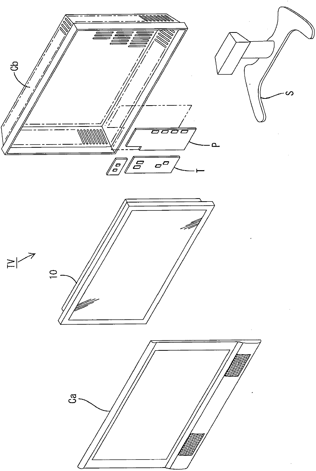
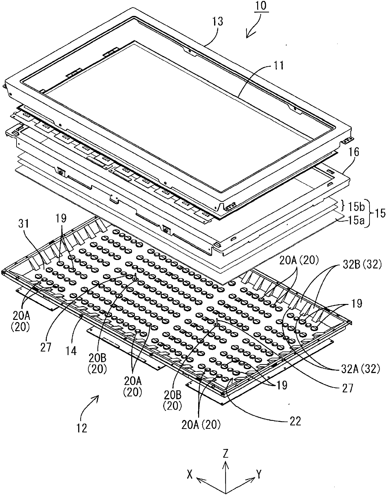
[0044]according to Figure 1 to Figure 10 Embodiment 1 of the present invention will be described. In this embodiment, a liquid crystal display device 10 is exemplified. In addition, X-axis, Y-axis, and Z-axis are drawn in a part of each drawing, and each axis direction is drawn as a common direction in each drawing. Additionally, the Figure 4 with Figure 5 The upper side shown in the figure is set as the front side, and the lower side in the figure is set as the back side.

[0045] The television receiver TV of this embodiment is such as figure 1 As shown, a liquid crystal display device 10 is provided; two front and back cases Ca, Cb of the liquid crystal display device 10 are sandwiched and accommodated; a power supply P; a tuner T; The liquid crystal display device 10 (display device) has a horizontally long square (rectangular) shape as a whole, and is housed in a vertically placed state. The liquid crystal display device 10 such as figure 2 As shown, a liquid c...

Embodiment approach 2

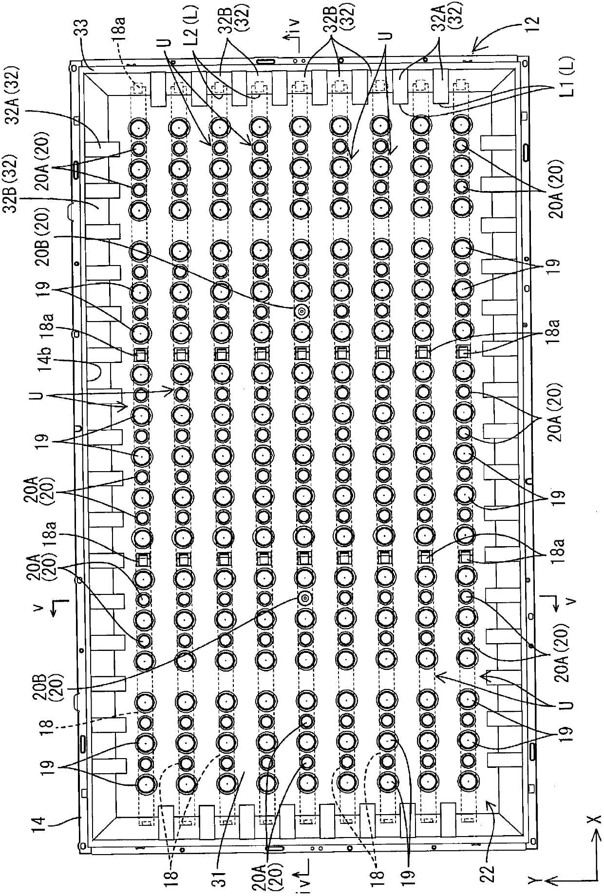
[0104] according to Figure 11 Embodiment 2 of the present invention will be described. The same reference numerals are assigned to the same parts as those in Embodiment 1, and repeated descriptions will be omitted. In the backlight unit 112 of the present embodiment, the shape of the boundary line L3 between the bottom portion 131 and the inclined portion 132 of the chassis reflection sheet 122 is different from that of the first embodiment. The boundary line L3 includes: a straight linear portion LA3 and a ridge portion LB3 formed by partially protruding the inclined portion 132 inwardly of the base 14, and the linear portion LA3 and the ridge portion LB3 are alternately arranged. This is nonlinear as a whole. The actions and effects of making the boundary line L3 nonlinear in this way are the same as those in the first embodiment described above, and therefore description thereof will be omitted.

[0105] In addition, in this embodiment, the bottom portion 131 and the in...


PUM


Abstract

Disclosed is an illumination device that is capable of suppressing uneven brightness. The illumination device is equipped with LEDs (17), a chassis (14) that houses the LEDs (17), and a light-reflecting sheet (22) for the chassis that is disposed on the inner surface of the chassis (14) and is capable of reflecting the light from the LEDs (17); and is characterized in that the light-reflecting sheet (22) for the chassis has a sheet bottom section (31) extending along the surface of a base plate (14a) and a sheet oblique section (32) extending from the edge of the sheet bottom section (31), in that the sheet oblique section (32) slants in relation to the sheet bottom section (31) toward the light emission side of a backlight device (12), and in that the optical reflectivity of a boundary section (F2), which is the region along the border line (L) between the sheet bottom section (31) and the sheet oblique section (32) and includes said border line (L), on the surface of the LED (17) side of the light-reflecting sheet (22) for the chassis is set higher than the optical reflectivity of separate-side neighboring sections (F1, F3) that neighbor on sides of the boundary section (F2) separated from the border line (L).

Description

technical field [0001] The present invention relates to an illuminating device, a display device and a television receiving device. Background technique [0002] Conventionally, a liquid crystal panel used in a liquid crystal display device such as a liquid crystal television does not emit light by itself, so a backlight device as an illumination device is separately required. It is well known that the backlight device is arranged on the back side (the side opposite to the display surface) of the liquid crystal panel, and is provided with: a base having an opening shape on the side of the liquid crystal panel; a plurality of light sources (such as cold cathode tubes, LEDs, etc.); ), which is arranged on the inner side of the bottom plate of the base; and a light reflection sheet, which is laid in the base to reflect light from the light source to the liquid crystal panel side. In addition, what is described in the following patent document 1 is known as an example of such a...

Claims


Application Information

Patent Timeline
Patent Type & Authority Applications(China)
IPC IPC(8): F21S2/00F21V5/00G02F1/13357H01L33/48F21Y101/02
CPCG02F1/133603G02F1/133605G02F1/133611
Inventor 松本慎司
Owner SHARP KK
Why Eureka
Try Eureka