Liquid crystal display device
A technology of liquid crystal display device and liquid crystal layer, applied in nonlinear optics, instruments, optics, etc., which can solve the problems of whitening, whitening, and unsightly gray scale of skin color
- Summary
- Abstract
- Description
- Claims
- Application Information
AI Technical Summary
Problems solved by technology
Method used
Image
Examples
Embodiment approach 1
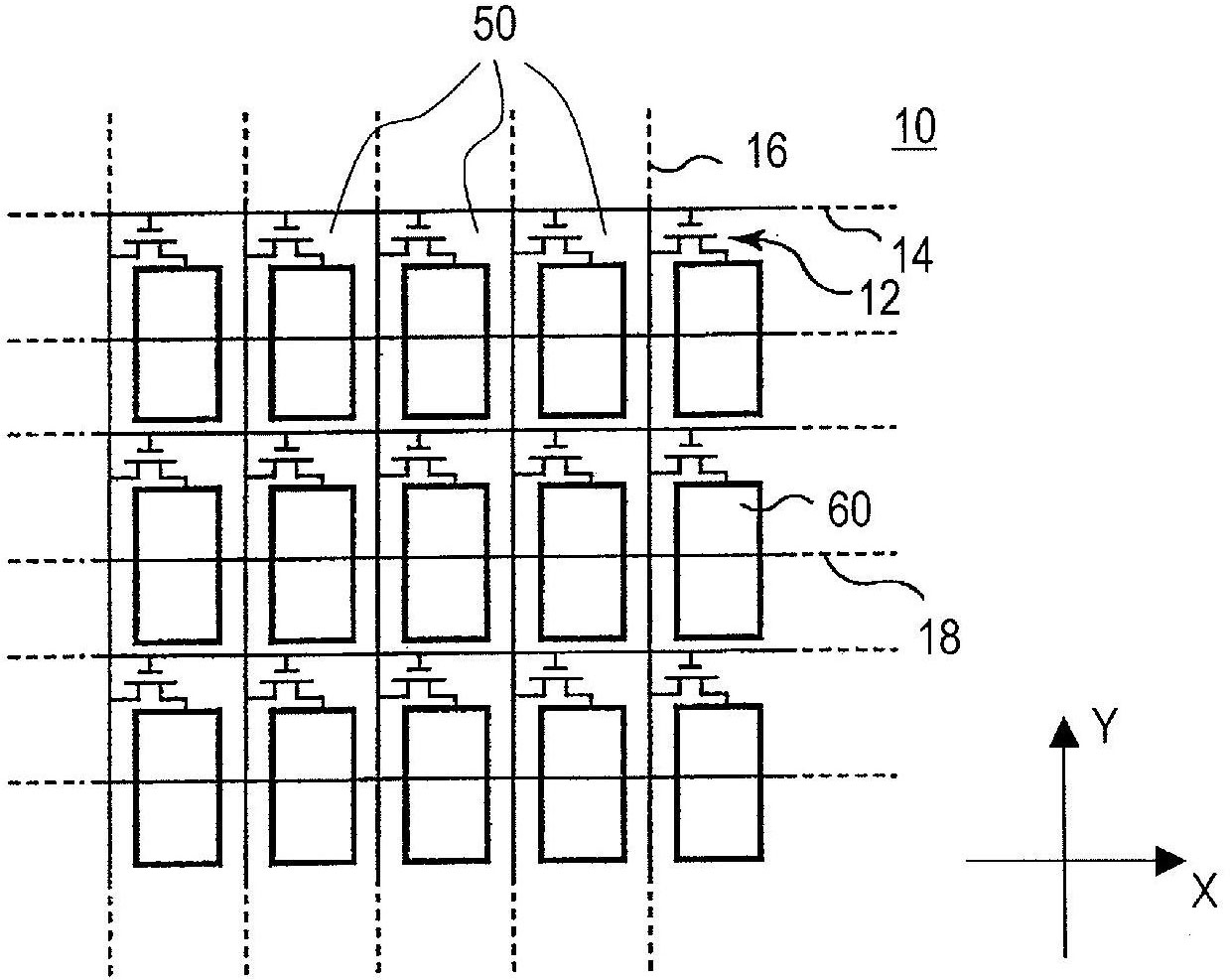
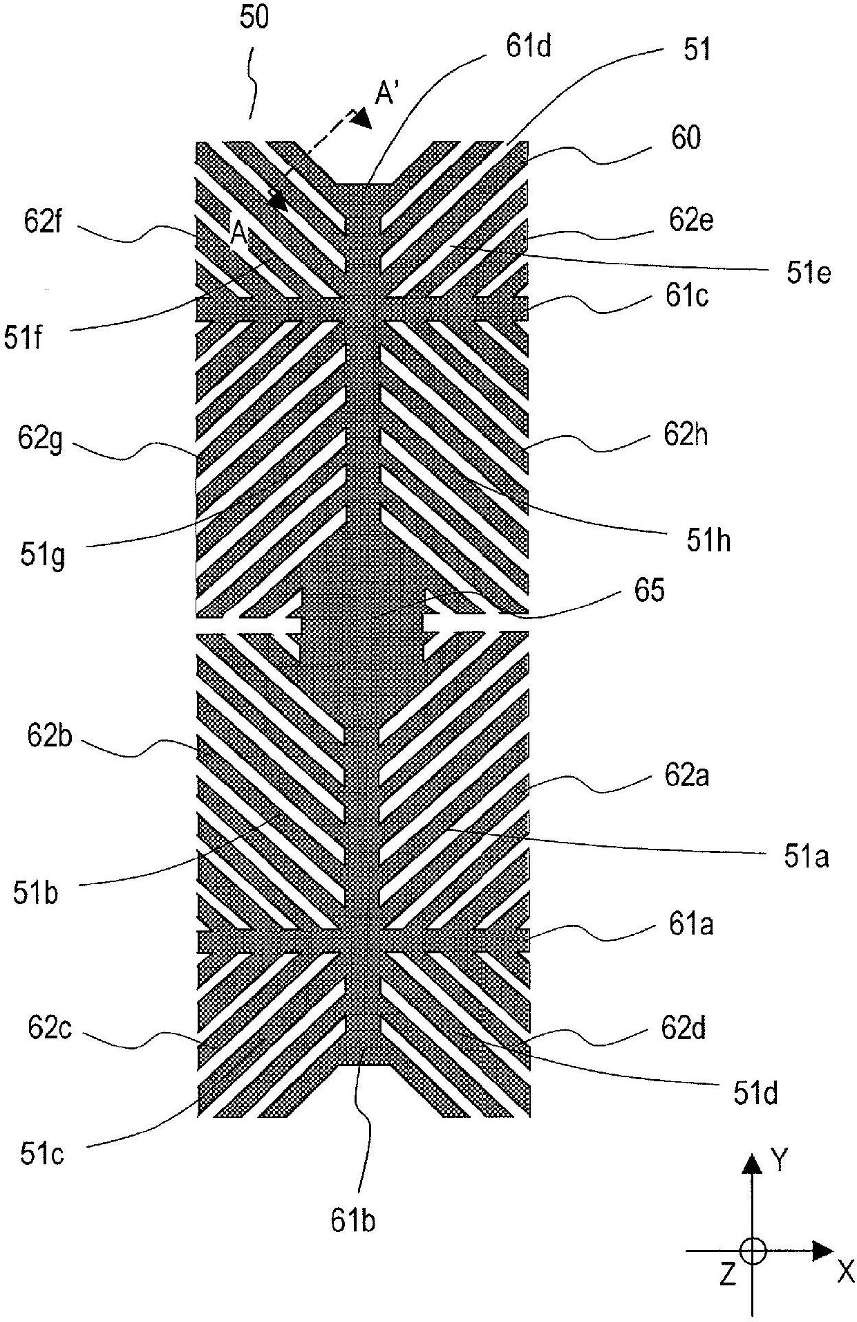
[0068] image 3 is a plan view showing the structure of the pixel electrode 60 of the liquid crystal display device 100 according to Embodiment 1 of the present invention, Figure 4 is for pixel 50 image 3Cross-sectional view of the structure of the A-A' section. In addition, in the description of all the embodiments of the present invention, the extension direction of the scanning line 14 ( image 3 The left and right direction) is the X direction, and the extension direction of the signal line 16 ( image 3 The vertical direction in ) is the Y direction, and the direction perpendicular to the substrate surface (including the TFT substrate 10 ) of the liquid crystal display device 100 is the Z direction. Also, in the positive X direction ( image 3 The direction from left to right) is the direction of azimuth 0°, and the azimuth is set counterclockwise. Positive Y direction ( image 3 The direction from bottom to top) is the direction of azimuth angle 90°.
[0069] A ...
Embodiment approach 2
[0110] Next, refer to Figure 10 ~ Figure 13 A liquid crystal display device 100 according to Embodiment 2 of the present invention will be described. In the following description of the embodiment, the same reference numerals are assigned to the same components or components having the same functions as those in the first embodiment, and descriptions thereof and descriptions of effects obtained therefrom are omitted. The liquid crystal display device 100 of Embodiment 2 includes the same components as those of Embodiment 1 except for the differences shown or described below.
[0111] Figure 10 (a) shows the shape of the common electrode 45 of one pixel 50 , and (b) shows the shape of the pixel electrode 60 of one pixel 50 . Figure 11(a) shows the common electrode 45 of the two pixels 50a and 50b adjacently arranged in the Y direction, and (b) shows the arrangement relationship between the common electrode 45 and the pixel electrode 60 of the two pixels 50a and 50b.
[01...
Embodiment approach 3
[0128] Next, refer to Figure 14 and Figure 15 A liquid crystal display device 100 according to Embodiment 3 of the present invention will be described. In the description of the following embodiments, the same components or components having the same functions as those in Embodiments 1 and 2 are assigned the same reference numerals, and descriptions thereof and descriptions of effects obtained therefrom are omitted. In addition, the liquid crystal display device 100 of Embodiment 3 includes the same components as those of Embodiment 1 or 2, except for the differences that will be illustrated or described below.
[0129] The shape of the pixel electrode in the liquid crystal display device 100 according to Embodiment 3 is the same as that of the pixel electrode in Embodiment 2, and therefore a detailed description thereof will be omitted.
[0130] Figure 14 (a) shows the common electrode 45 of the two pixels 50a and 50b adjacently arranged in the Y direction, and (b) show...
PUM
 Abstract
Description
Claims
Application Information
 - R&D
- Intellectual Property
- Life Sciences
- Materials
- Tech Scout
- Unparalleled Data Quality
- Higher Quality Content
- 60% Fewer Hallucinations
Browse by: Latest US Patents, China's latest patents, Technical Efficacy Thesaurus, Application Domain, Technology Topic, Popular Technical Reports.
© 2025 PatSnap. All rights reserved.Legal|Privacy policy|Modern Slavery Act Transparency Statement|Sitemap|About US| Contact US: help@patsnap.com


