Shoe cabinet having ventilating pipes and blowing air from bottom to top

A bottom-up, ventilation duct technology, applied in the field of shoe cabinets with ventilation ducts and bottom-up blowing, can solve the problems of easy damage to shoes, dryness, poor dehumidification effect, strong heat, etc., and achieve uniform distribution of wind , Dehumidification effect is good, the effect of protecting shoes

Inactive Publication Date: 2012-09-19
徐金保
View PDF0 Cites 5 Cited by
  • Summary
  • Abstract
  • Description
  • Claims
  • Application Information

AI Technical Summary

Problems solved by technology

[0003] At present, the smart electronic shoe cabinets on the market mainly have an air vent at the bottom of the shoe cabinet. Although there is an air duct, the function of the air duct is not fully utilized.
In the shoe cabinet, due to the influence of multi-layer shoe racks, the circulation effect is poor. The lower layer of the shoe rack is exposed to wind and heat, and the middle is weak, resulting in uneven wind and heat in the shoe cabinet, and poor sterilization, disinfection, deodorization, and dehumidification effects.
Its biggest disadvantage is that the shoes are heated at high temperature, dehumidified and dried by temperature.
In this way, not only the air-drying speed is slow, but also the shoes are easy to be damaged; due to the high temperature, the leather shoes will emit a peculiar smell, and the drying and dehumidification effect is poor.

Method used


Image

  • Shoe cabinet having ventilating pipes and blowing air from bottom to top
  • Shoe cabinet having ventilating pipes and blowing air from bottom to top

Examples


Embodiment Construction

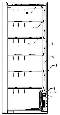
[0012] In conjunction with the accompanying drawings, a shoe cabinet with ventilation ducts and blowing from bottom to top according to the present invention includes a shoe cabinet main body 3, a shoe rack support plate 9, and a blower 1 and a heater 2. The blower is arranged on the shoe cabinet main body 3 In the square box 5 connected to the air duct at the bottom of the interior, an air duct 6 is set at the rear of the shoe cabinet main body 1, and the wind blown by the blower 1 can enter the air duct through the heater 2, and a ventilation hole is arranged on the air duct, and the ventilation hole Automatic switching device 7 is installed; Shoe rack supporting plate 9 is provided with ventilation pipe 8, and one end of this ventilation pipe 8 is connected with supporting plate, and the other end is inserted in the ventilation hole of air duct 6, and communicates with air duct 6.

[0013] The automatic switching device 7 includes a spring 4 and a cover plate. One end of the...


PUM


Abstract

The invention relates to a shoe cabinet having ventilating pipes and blowing air from bottom to top. The shoe cabinet comprises a shoe cabinet main body (3) and shoe rack support plates (9), wherein an air flue (6) is arranged on the shoe cabinet main body (3), an air inlet of an air flue (5) is arranged at the lower part of the shoe cabinet, a heater (2) is arranged at the air inlet, the shoe rack support plates are provided with ventilating pipes (8) communicated with the air flue (5), one ends of the ventilating pipes (8) are connected with the shoe rack support plates (9), and the other ends of the ventilating pipes (8) are inserted into ventilating holes of the air flue (6). Compared with the prior art, the invention has the remarkable advantages that: firstly, air blown from an air blower raises from bottom to top, and hot air naturally raises due to small specific weight and rapidly enters a cabinet body; secondly, air disperses in the shoe cabinet through the air flues and the ventilating pipes, and is uniformly distributed in the shoe cabinet, thus air drying and dehumidifying effects are good; and thirdly, a heating sheet is arranged at the air outlet of the air blower, the blown air can be heated, and the hot air can not cause ageing or damage to shoes, thus shoes are effectively protected.

Description

technical field [0001] The invention relates to a bottom-up blowing shoe cabinet with a ventilation duct, in particular to a bottom-up blowing shoe cabinet with a ventilation duct. Background technique [0002] Since China's reform and opening up, people's living conditions and living standards have been continuously improved. More and more consumers, especially some high-end customers, are no longer satisfied with conventional home furnishing needs. They need more sophisticated home furnishing products. The concept of smart home has begun Known and used by more and more people. Smart home will become a new trend in the future. [0003] At present, the smart electronic shoe cabinets on the market mainly have an air vent at the bottom of the shoe cabinet. Although there is an air duct, the function of the air duct has not been fully utilized. In the shoe cabinet, due to the influence of multi-layer shoe racks, the circulation effect is poor. The lower layer of the shoe rack...

Claims


Application Information

Patent Timeline
Patent Type & Authority Applications(China)
IPC IPC(8): A47B61/04A47B97/00
Inventor 徐金保
Owner 徐金保
Why Eureka
Try Eureka