Leaching tank stirring device having defoaming function

The technology of a stirring device and a leaching tank is applied in the directions of mixers with rotary stirring devices, accessories of mixers, improvement of process efficiency, etc., which can solve the problem of foam, adverse effects of the next process, and unsatisfactory defoaming effect of small bubbles. And other issues

Inactive Publication Date: 2012-09-19
SUZHOU JINXIANG TITANIUM EQUIP
View PDF4 Cites 9 Cited by
  • Summary
  • Abstract
  • Description
  • Claims
  • Application Information

AI Technical Summary

Problems solved by technology

The stirred mixed solution in the leaching tank is likely to contain foam, which will have adverse effects on the next process if it is not removed
The traditional stirring device does not have

Method used


Image

  • Leaching tank stirring device having defoaming function
  • Leaching tank stirring device having defoaming function
  • Leaching tank stirring device having defoaming function

Examples


Embodiment Construction

[0015] The present invention will now be described in further detail with reference to the drawings and embodiments. These drawings are simplified schematic diagrams, which only illustrate the basic structure of the present invention in a schematic manner, and therefore only show the constitutions related to the present invention.

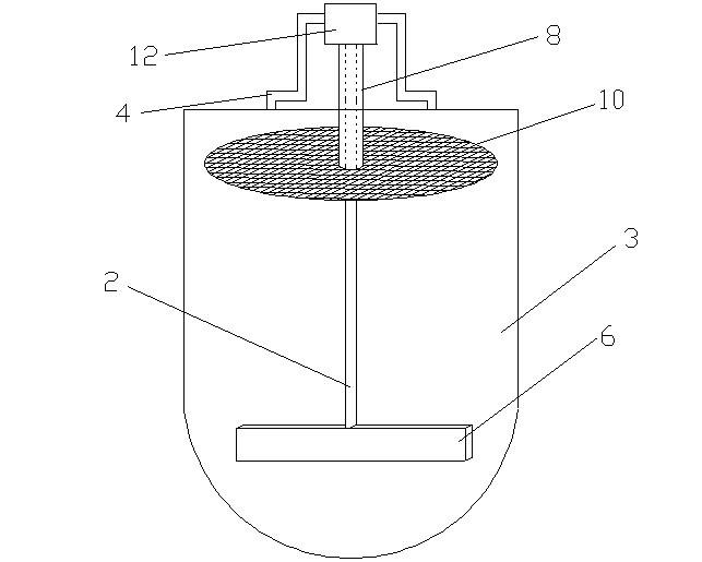
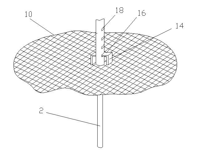
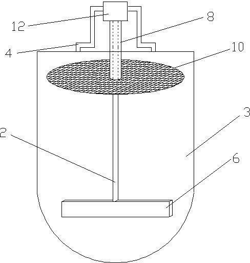
[0016] Such as Figure 1-2 As shown, an leaching tank stirring device with defoaming function of the present invention includes a longitudinal stirring shaft 2, a first motor arranged at one end of the stirring shaft 2, a bracket 4 for fixing the entire stirring device, and a The other end of the shaft 2 is a stirring paddle 6 with the stirring shaft 2 as the rotating shaft. The stirring shaft 2 is sheathed with a cylindrical support shaft 8 fixed to the bracket 4, and the support shaft 8 is provided with a sheet-shaped defoaming net 10 perpendicular to the axis of the support shaft 8. The first motor is located in a case 12 arranged at one end of th...


PUM


Abstract

The invention relates to a leaching tank stirring device having a defoaming function. The stirring device comprises a long stirring shaft, a first motor, a bracket and stirring vanes, wherein the first motor and the bracket are arranged at one end of the stirring shaft; the bracket is used for fixing the whole stirring device; the stirring vanes taking the stirring shaft as a rotary shaft are arranged on the other end of the stirring shaft; and a cylindrical supporting shaft fixed on the bracket is sleeved outside the stirring shaft, and the supporting shaft is provided with a flaky defoaming mesh perpendicular to the axis of the supporting shaft. According to the leaching tank, the defoaming mesh is integrated on the stirring shaft of the conventional stirring device, so the foam floating on the surface of mixed liquid can be removed when the stirring vanes rotate or stop rotating. The defoaming mesh has a rotary structure independent of the stirring shaft, and the axial height is adjustable, so the transverse cutting force for foam is increased, the degree of adaptability to the tanks with different heights and the mixed liquid with different liquid levels is improved, and the defoaming effect is strengthened.

Description

Technical field [0001] The invention relates to a mixture stirring device, in particular to a stirring device used in leaching tanks for chemical industry and metallurgy. Background technique [0002] The leaching tank is a liquid-solid reactor that realizes the leaching operation under normal pressure and temperature below 373K. The leaching tanks that are widely used in non-ferrous metal extraction and metallurgy mainly include percolation tanks, compressed air stirring tanks, mechanical stirring tanks, air and mechanical combined stirring tanks and Kamal towers. The leaching tank stirring device mainly includes a stirring shaft, a motor that drives the rotation of the stirring shaft at one end of the stirring shaft, and a stirring paddle at the other end of the stirring shaft that is responsible for the stirring work. The mixed liquid after being stirred in the leaching tank is very likely to contain foam. If it is not removed, it will adversely affect the next process. The ...

Claims


Application Information

Patent Timeline
IPC IPC(8): B01F7/18B01F15/00C22B3/02
CPCY02P10/20
Inventor 范祥荣
Owner SUZHOU JINXIANG TITANIUM EQUIP
Why Eureka
Try Eureka