
Light irradiating device

A light irradiation device and light reflection technology, which is applied in the fields of electrical components, semiconductor/solid-state device manufacturing, circuits, etc., can solve problems such as difficult light cleaning and processing

Active Publication Date: 2012-09-19
USHIO DENKI KK
View PDF8 Cites 2 Cited by
  • Summary
  • Abstract
  • Description
  • Claims
  • Application Information

AI Technical Summary

Problems solved by technology

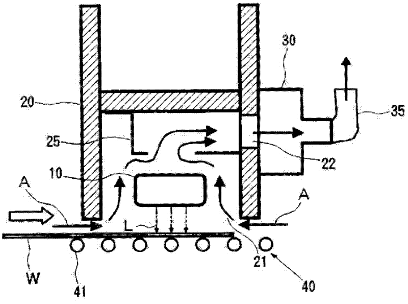
[0007] However, in the light irradiation device described above, it has been found that there is a problem that pollutants such as organic matter adhering to the object to be irradiated and pollutants such as AMC (Airborne Molecular Contaminants) contained in the air introduced into the lampshade are separated by The reaction is activated by the ultraviolet rays from the excimer lamp, and the reaction product accumulates on the inner wall surface of the lampshade, then separates from the inner wall surface of the lampshade and adheres to the object to be irradiated, so it is difficult to reliably complete the required optical cleaning treatment.

Method used


Image

  • Light irradiating device
  • Light irradiating device
  • Light irradiating device

Examples


Embodiment 1

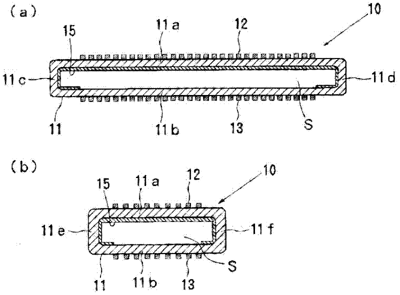
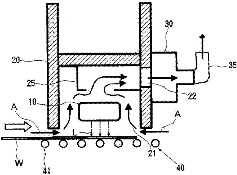
[0066] according to figure 1 and figure 2 The composition of the lampshade has a width of 160mm, a height of 250mm, a height of 100mm for the excimer lamp, and a total length (depth) of 3000mm; Light irradiation device of excimer lamp with a length of 2200mm. The excimer lamp of this light irradiation device seals xenon gas in the inside of the discharge vessel, and, as a light shielding unit, covers the upper wall of the discharge vessel and the entire inner surface of each of the four side walls and the peripheral portion of the lower wall. The inner surface forms an ultraviolet shielding film. Furthermore, a glass substrate for liquid crystal is used as the object to be irradiated, and the lamp power of the excimer lamp is 1.6kW, and the ultraviolet irradiation on the outer surface of the discharge vessel is 150mW / cm 2 , The distance between the excimer lamp and the object to be irradiated is 4mm, the gas exhaust volume is 3000l / min, and the conveying speed of the glass...

Embodiment 2

[0070] Except that the position where the ultraviolet shielding film is formed is changed to the entire outer surface of the upper wall and four side walls of the discharge vessel and the outer surface of the peripheral portion of the lower wall, a light irradiation system with the same structure as in Example 1 is made. device. In addition, a glass substrate for liquid crystal was used as the object to be irradiated, and the glass substrate was cleaned under the same conditions as in Example 1, and the contact angles of the surfaces of the glass substrate before and after the cleaning treatment were measured.

[0071] As a result, the contact angle of the surface of the glass substrate was 40° before the cleaning treatment, but was 2° after the cleaning treatment, and it was confirmed that a high cleaning treatment ability was obtained.

[0072] Furthermore, the light irradiation device was operated continuously for 6 months, and the cleaning treatment of the glass substrate ...


PUM

PropertyMeasurementUnit
Contact angleaaaaaaaaaa

Abstract

Provided is a light irradiating device capable of preventing or suppressing a reaction product between pollutant such as organics attached to an irradiated object and pollutant contained in the atmosphere from being attached to the irradiated object, so as to reliably complete required light cleaning processing. The light irradiating device is characterized by comprising: an excimer lamp; a lampshade which is arranged to surround the excimer lamp and has an opening used for emitting a light from the excimer lamp towards outside and a gas outlet used for discharging the gas at an inner part; and a gas discharge mechanism used for leading the atmosphere towards the inner part of the lampshade from the opening of the lampshade and discharging the atmosphere from the gas outlet of the lampshade; wherein, the excimer lamp is provided with a light shield unit used for shielding irradiated lights in the way that the irradiated lights of the excimer lamp can not irradiate to a wall forming a gas flow path in the lampshade.

Description

technical field [0001] The present invention relates to a light irradiation device suitable for optically cleaning the surface of substrates such as wafers and glass substrates in the manufacturing process of semiconductor elements and flat panel displays. Background technique [0002] In the manufacturing process of semiconductor elements, flat panel displays such as liquid crystal display devices, solar cells, etc., in order to form a thin film with high adhesion to substrates such as silicon wafers and glass substrates, the surface of the substrate is generally cleaned. The treatment is performed to remove pollutants such as organic substances present on the surface of the substrate. As a method of cleaning the surface of the substrate, a dry cleaning method that does not use water, organic solvents, etc. is widely used. As this dry cleaning method, it is known to irradiate the surface of the object to be processed with excimer light from an excimer lamp, and to clean the...

Claims


Application Information

Patent Timeline
IPC IPC(8): B08B7/00
CPCH01L21/02041H01L21/268H01L21/67034
Inventor 远藤真一山森贤治石原肇川口真孝
Owner USHIO DENKI KK
Learn More