Storage, toner passage, and image forming apparatus
A technology of toner and storage part, which is applied in the field of toner passage, image forming device and storage part, which can solve the problems of image quality reduction, influence on toner chargeability, complexity, etc., and achieve the effect of efficient use
- Summary
- Abstract
- Description
- Claims
- Application Information
AI Technical Summary
Problems solved by technology
Method used
Image
Examples
no. 1 Embodiment
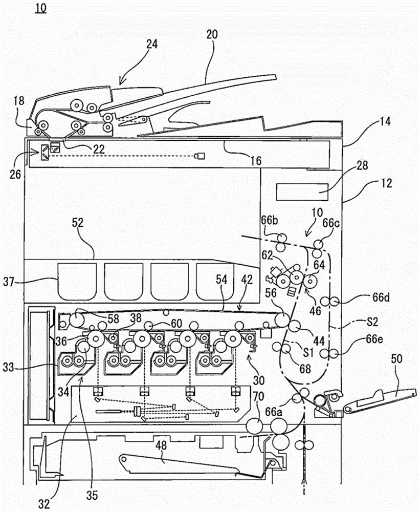
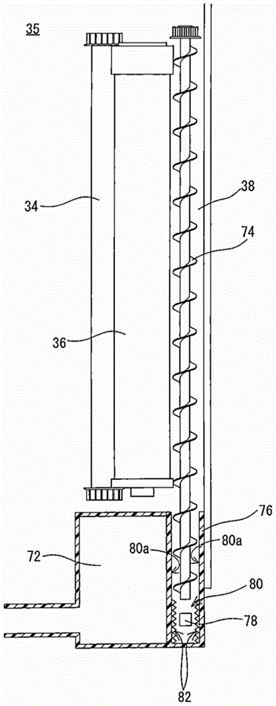
[0063] According to the first embodiment of the present invention is applied to figure 2 The shown processing unit 35 includes a cleaner unit 38 . The processing unit 35 includes the developing roller 34, the photosensitive drum 36, the cleaner unit 38, and the like for each color as described above. The cleaner unit 38 sends toner (waste toner) that remains on the surface of the photosensitive drum 36 after development and transfer and is removed from the surface of the photosensitive drum 36 by, for example, a cleaning roller (not shown) or the like. To the waste toner box 72 provided inside the multifunction machine main body 12 on the front side of the photosensitive drum 36 and the intermediate transfer roller 60 .
[0064] From figure 2 It can be seen that the cleaner unit 38 includes the toner conveying screw 74, which is driven to rotate at one end side (inner side of the main body 12), and sends the waste toner to the nearer side along with the rotation. Inside t...
no. 2 Embodiment
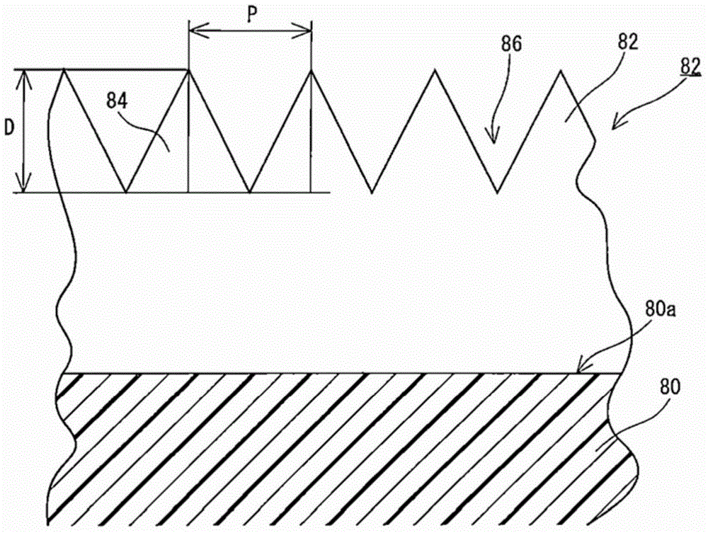
[0087] Figure 6 Shows the second embodiment. as previously referenced figure 1 As described above, from the toner cartridge 37 via the relay pipe 104 ( Figure 6 ) supplies the toner to the casing 33 of the developing roller 34 . Moreover, in Figure 6 In the shown second embodiment, the inner wall surface of the relay pipe 104 is implemented with image 3 The moth-eye structure 82 is illustrated.
[0088] When the toner is supplied from the toner cartridge 37 to the casing 33 of the developing unit via the relay pipe 104, it is not fluid like waste toner, nor is it transported from bottom to top against gravity. Toner, but there are still cases where the toner cannot be smoothly conveyed. This is caused by toner adhering to the inner wall of the relay pipe. This is because the surface of toner is charged by external additives (functional fine particles) although it is not waste toner, so even if the fluidity is good, it adheres due to its high charging performance. I...
no. 3 Embodiment
[0092] In the third embodiment, such as Figure 6 As shown, a moth-eye structure 82 is further implemented on the inner wall surface of the casing 33 .
PUM
 Abstract
Description
Claims
Application Information
 - R&D Engineer
- R&D Manager
- IP Professional
- Industry Leading Data Capabilities
- Powerful AI technology
- Patent DNA Extraction
Browse by: Latest US Patents, China's latest patents, Technical Efficacy Thesaurus, Application Domain, Technology Topic, Popular Technical Reports.
© 2024 PatSnap. All rights reserved.Legal|Privacy policy|Modern Slavery Act Transparency Statement|Sitemap|About US| Contact US: help@patsnap.com


