Vehicle-mounted periphery recognition device

A technology for identifying devices and vehicles, applied in optical observation devices, vehicle parts, transportation and packaging, etc., can solve the problems of misidentification or non-identification, high possibility of misidentification or misidentification, misidentification, etc., to reduce misidentification or unrecognized, improved recognition function, and reduced production costs

Active Publication Date: 2012-09-19
HYUNDAI MOBIS CO LTD
View PDF6 Cites 2 Cited by
  • Summary
  • Abstract
  • Description
  • Claims
  • Application Information

AI Technical Summary

Problems solved by technology

[0007] However, due to the limitations of the ultrasonic sensor or the limitations of the installation position and direction, there is a problem of high possibility of misidentification or non-identification
[0008] That is, when other objects around or ultrasonic sensors installed on other vehicles are in operation; when the road slope is very large; when the ultrasonic sensor is exposed to the outside of the vehicle and the sensor surface is contaminated; when the ultrasonic sensor is loaded at a height or position and angle are deformed; Sensor limitations or restricted loading position and orientation, high chance of misidentification or non-identification
[0009] In addition, due to the limitation of the loading position and direction of the laser sensor, EBA may misidentify or fail to identify very low approaching obstacles to the front, and there are such problems

Method used


Image

  • Vehicle-mounted periphery recognition device
  • Vehicle-mounted periphery recognition device
  • Vehicle-mounted periphery recognition device

Examples


Embodiment Construction

[0031] The following will describe in detail with reference to the accompanying drawings of a vehicle-mounted peripheral recognition device according to an embodiment of the present invention. In this process, the thickness of lines or the size of constituent elements shown in the drawings may be exaggerated for clarity and convenience of description. The following terms are defined in consideration of the functions in the present invention, and may vary depending on the intention of the user or operator, or customary practice. Therefore, these terms should be defined based on the entire content of this specification.

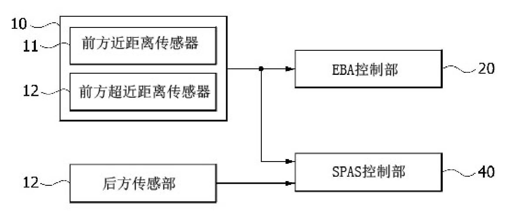
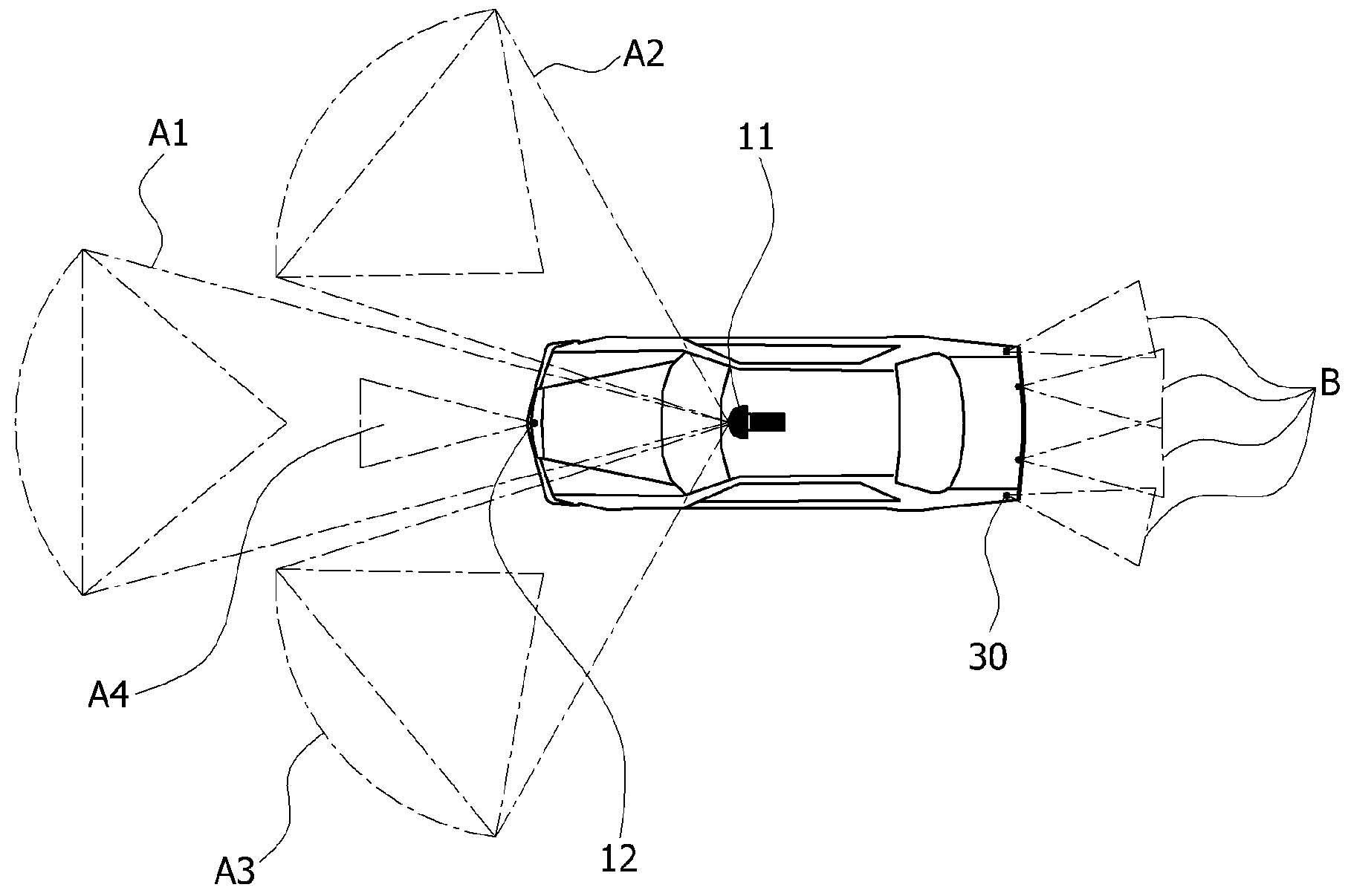
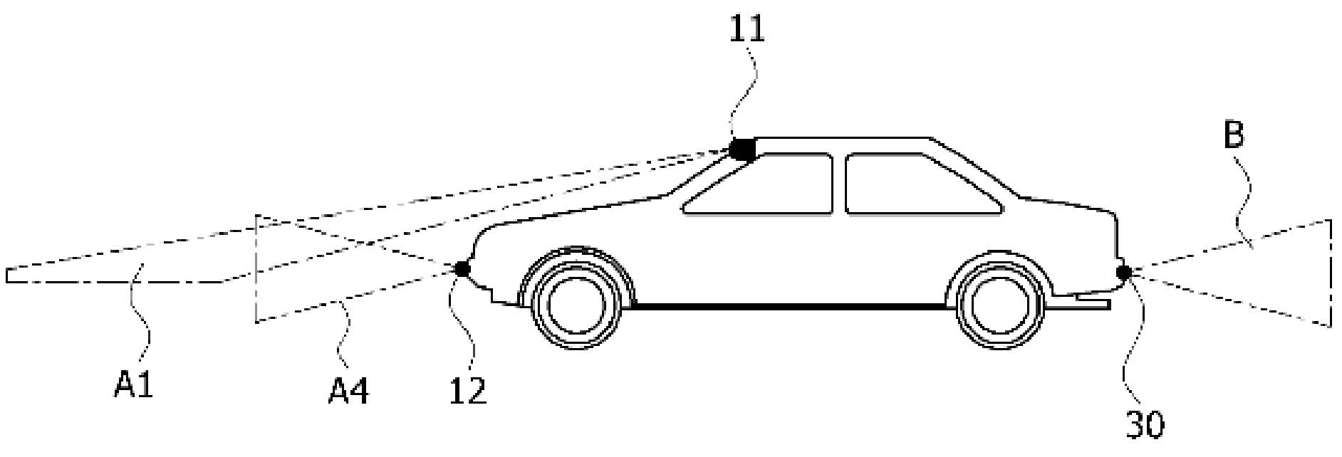
[0032] figure 1 It is a structural diagram showing a vehicle-mounted peripheral recognition device according to an embodiment of the present invention. figure 2 According to an embodiment of the present invention, it is a top view showing the sensing range based on the arrangement structure of the ultrasonic sensor and the laser sensor in the vehicle. imag...


PUM


Abstract

The present invention relates to a vehicle-mounted periphery recognition device, comprising: a front sensing part consisting of a front close range sensor installed on a vehicle wind shield for sensing barriers within a close range in front of a central part of the vehicle and in front of a left-right side of the vehicle and a front ultra close range sensor installed on a bumper in front of the vehicle for sensing barriers within an ultra close range in front of the vehicle; a rear sensing part comprising a rear ultra close range sensor used for sensing barriers within an ultra close range in rear of the vehicle; a first control part used for sensing a parking space according to a sensing signal input by the front sensing part and a sensing signal input by the rear sensing part; and a second control part used for sensing the parking space according to the sensing signal input by the front sensing part. Therefore, recognition functions of a smart parking assistance system and an emergency brake assist can be improved.

Description

technical field [0001] The invention relates to a vehicle-mounted peripheral identification device, which combines a laser sensor and an ultrasonic sensor to improve the identification performance of parking areas and surrounding obstacles. Background technique [0002] Generally, the Smart Parking Assistance System (Smart Parking Assistance System; hereinafter referred to as "SPAS") detects the parking space, automatically controls the steering wheel, and cooperates with the driver to control the brakes to complete the parking action. [0003] SPAS installs multiple ultrasonic sensors on the car in order to identify obstacles and measure distances, and to detect parking areas and obstacles in front of, behind and on the side of the vehicle. [0004] On the one hand, Emergency Brake Assist (hereinafter referred to as "EBA") is a system that recognizes obstacles approaching ahead and automatically decelerates. In order to detect obstacles ahead, a laser sensor is installed in...

Claims


Application Information

Patent Timeline
Patent Type & Authority Applications(China)
IPC IPC(8): B60R1/00B60R11/00
CPCB60W30/06B60W40/02B60W2420/54B60W2420/62
Inventor 朴敏荣闵丙培
Owner HYUNDAI MOBIS CO LTD
Why Eureka
Try Eureka